Air bag device for knee protection

an airbag device and knee protection technology, which is applied in the direction of pedestrian/occupant safety arrangement, vehicular safety arrangments, vehicle components, etc., can solve the problems of affecting the safety of drivers, difficult to arrange a pad or an airbag smoothly between the column cover and the knee of drivers, etc., to reduce the protrusion of the knee and the pressure on the knee.

Inactive Publication Date: 2005-09-13
TOYODA GOSEI CO LTD
View PDF19 Cites 41 Cited by
  • Summary
  • Abstract
  • Description
  • Claims
  • Application Information

AI Technical Summary

Benefits of technology

[0010]In the first knee protecting airbag device according to the present invention, the airbag is constructed to cover only the substantial lower surface of the column cover protruded to the driver's side. Therefore, the airbag can minimize its capacity without deteriorating the protection performance of the knee of the driver. As a result, it is possible to shorten the time period till the expansion and inflation are completed.
[0034]In the fourth knee protecting airbag device according to the present invention, the upper portion in the airbag covers the portion from the upper portion of the knee of the driver to the vicinity of the thigh, and the lower portion in the airbag covers the portion from the lower portion of the knee of the driver to the vicinity of the leg. Therefore, the airbag expanded and inflated protects the knee of the driver properly over a wide range. While the airbag is being expanded and inflated, on the other hand, the upper portion completes the expansion and inflation while ascending along the column cover lower surface, and the lower portion completes the expansion and inflation while descending along the panel. As a result, the airbag suppresses the protrusion to the knee and the pressure on the knee of the driver.

Problems solved by technology

On the other hand, when the device acts, the driver mostly depresses a brake pedal.
Therefore, it may be difficult to arrange a pad or an airbag smoothly between the column cover and the knee of the driver.

Method used


Image

  • Air bag device for knee protection
  • Air bag device for knee protection
  • Air bag device for knee protection

Examples


first embodiment

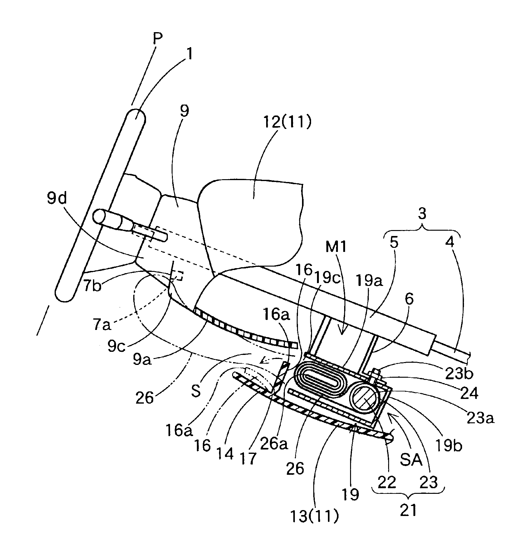
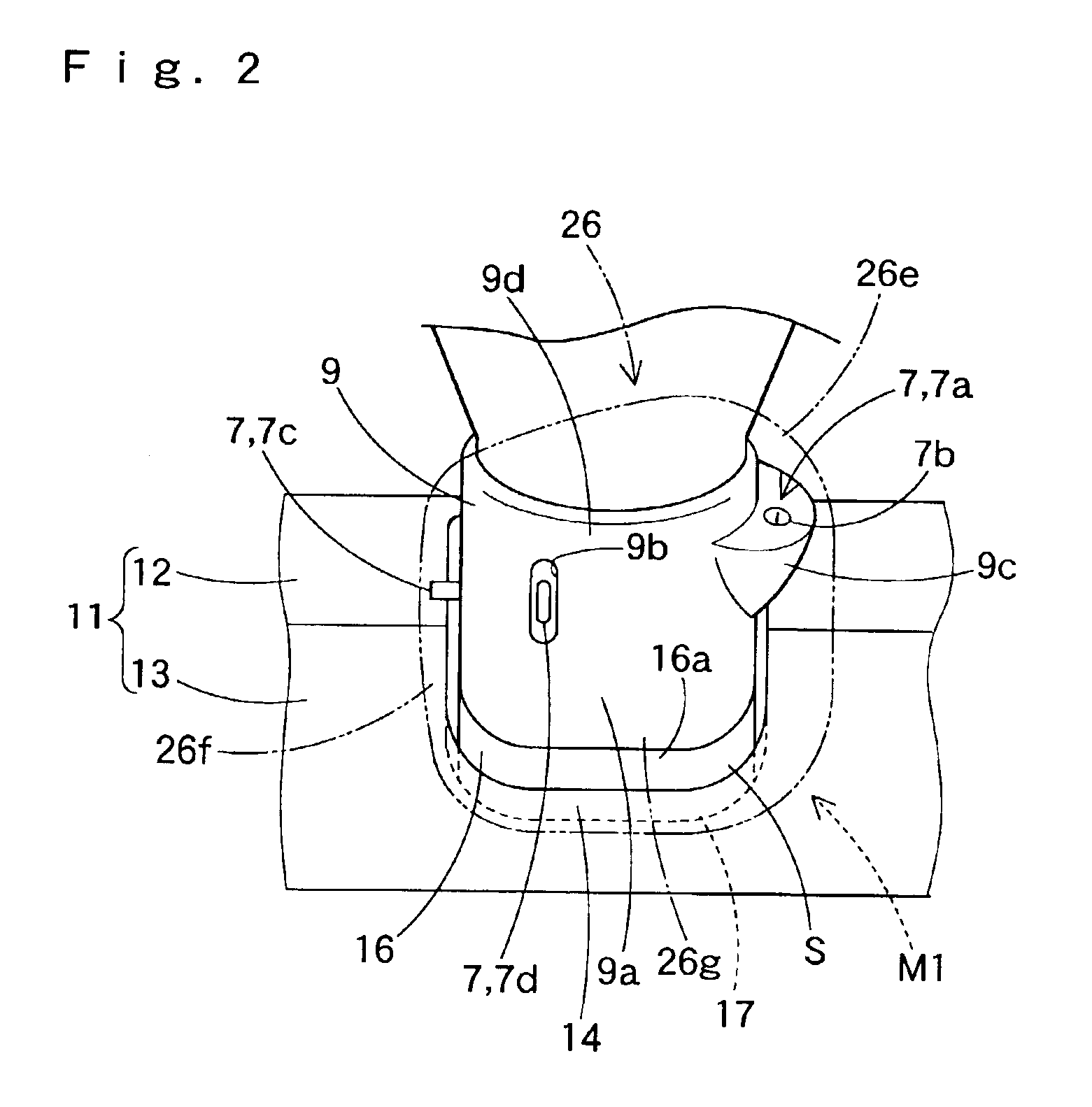
[0108]In the knee protecting airbag device M1 of the first embodiment, the airbag 26 is constructed to cover the column cover 9 protruded to the driver side exclusively on the side of substantial lower surface 9a of the column cover 9. Therefore, the airbag 26 can minimize its capacity without deteriorating the protection performance of the knee of the driver. As a result, the airbag 26 is able to shorten the time period required for completing the expansion and inflation.

[0109]Moreover, the airbag 26 takes such a generally plate shape when completed the inflation as covers only the lower surface 9a of the column cover 9. Even if the knee of the driver is close to the column cover 9 when the driver depresses a brake pedal, therefore, the expanded and inflated airbag 26 is smoothly arranged in a narrow space between the knee of the driver and the column cover lower surface 9a without interfering with the knee of the driver. Especially at the expanding and inflating time, the airbag 2...

second embodiment

[0129]In the second embodiment, moreover, the hinge portion 17A at the opening time is so arranged at the lower end side of the door portion 16A that the door portion 16A covering the folded airbag 26 may be opened downward. In this construction, the door portion 16A is opened from the side of its upper end 16a by the push of the airbag 26 being expanded and inflated. At the beginning of opening of the door portion 16A, therefore, the airbag 26 being expanded and inflated is protruded from the upper side of an open area OA of the door portion 16A. Specifically, the airbag 26 being expanded and inflated is easily protruded upward. As a result, the airbag 26 is smoothly expanded and inflated while rising along the side of the column cover lower surface 9a.

[0130]On the other hand, in the first and second embodiments, the door portions 16 and 16A are constructed to play a role of the guide plate portion to guide the airbag 26 to expand and inflate along the column cover lower surface 9...

third embodiment

[0134]In this airbag device M3 of the third embodiment, the airbag 26B is expanded and inflated while rising upward from the lower side below the column cover 9 along the column cover lower surface 9a to the vicinity of the rear end 9d.

[0135]The airbag 26B having completed the expansion and inflation covers not only the column cover lower surface 9a but also a part of the dashboard 11 near the column cover 9. In short, the airbag 26B covers the side of the column cover lower surface 9a over a wide range. Therefore, the airbag 26B protects a wider range than the airbag 26. In other words, the airbag 26B protects the knee of the driver effectively over a wide range. Especially in the third embodiment, the key cylinder 61 and the release lever 62 to form the hard portion 60 are covered with the cover portions 26e and 26f even if they are arranged in the upper panel 12A and the lower panel 13A. Therefore, the airbag 26B can protect the knee of the driver properly from the members 61 an...


PUM


Abstract

A knee protecting airbag device (M1), wherein an airbag (26) covers the substantial lower surface (9a) of a column cover (9) protruded to a driver side. Therefore, the airbag is minimized in the capacity without deteriorating the protection of the knee of the driver. As a result, it is possible to shorten the time period required for the airbag to complete the expansion and inflation. The airbag has a generally plate shape capable of covering at least the lower surface of the column cover when it completes the inflation. Even if the knee of the driver comes close to the column cover when the driver depresses a brake pedal or the like, the airbag being expanded and inflated is smoothly arranged in a narrow space between the knee of the driver and the column cover lower surface without interfering with the knee of the driver. With the knee protecting airbag device according to the present invention, therefore, the airbag is rapidly expanded and inflated in the narrow space between the column cover and the knee of the driver thereby to protect the knee of the driver properly.

Description

BACKGROUND OF THE INVENTION[0001]1. Field of the Invention[0002]The present invention relates to a knee protecting airbag device in which an airbag to be expanded and inflated with an inflating gas let in protects the knee of a driver.[0003]2. Description of Related Art[0004]In the prior art, the device for protecting the knee of a driver is known in Japanese Patent Laid-Open No. 6-32195, EP Publication No. 0684167A1, EP Publication No. 0818360A1 and so on. In the prior art, more specifically, there is a device which has a pad near a column cover below a steering wheel to protrude to hold the knee of the driver when activated. There is another device which has an airbag to expand and inflate to protect the knee of the driver when activated.[0005]However, the knee protecting devices of the prior art have a room for further improvement in the proper protection of the knee of the driver although the activated pad or airbag covers a wide area.[0006]More specifically, there are partially...

Claims


Application Information

Patent Timeline
Patent Type & Authority Patents(United States)
IPC IPC(8): B60R21/16B60R21/20B60R21/203B60R21/206B60R21/217B60R21/233B60R21/2334B60R21/2338B60R21/237
CPCB60R21/206B60R21/216B60R21/233B60R21/2338B60R21/2346B60R21/237B60R21/215B60R21/2165B60R21/2171B60R2021/23169B60R2021/23316B60R2021/23324B60R2021/23382B60R2021/23386
Inventor TAKIMOTO, MASAHIROKOYAMA, TORU
Owner TOYODA GOSEI CO LTD
Why Eureka
Try Eureka