Image processing spout control system

a control system and image technology, applied in the field of image processing spout control system, can solve the problems of not processing any image signal, unable to process any image signal, and difficulty for the operator/driver of a material collection vehicl

Active Publication Date: 2005-09-13
DEERE & CO
View PDF23 Cites 139 Cited by
  • Summary
  • Abstract
  • Description
  • Claims
  • Application Information

AI Technical Summary

Benefits of technology

[0010]These and other objects are achieved by the present invention, wherein a spout control system controls and aims a spout and cap of a crop harvesting vehicle with respect to a separate crop hauling vehicle moving with the harvesting vehicle. The control system includes at least one video camera which is mounted on or near the end of a pivotal cap on an end of the spout and which views a

Problems solved by technology

It is difficult for the operator/driver of a material collecting vehicle, such as a forage harvester crop harvesting vehicle, to control the positioning of the crop discharge spout to achieve desired and/or even filling of a separate material hauling vehicle or crop hauling vehicle which moves along with the collecting or harvesting vehicle.
However, this system does not process any image signals and generate an automatic spout control signal as a function of a processed image.
However, this system als

Method used


Image

  • Image processing spout control system
  • Image processing spout control system
  • Image processing spout control system

Examples


Embodiment Construction

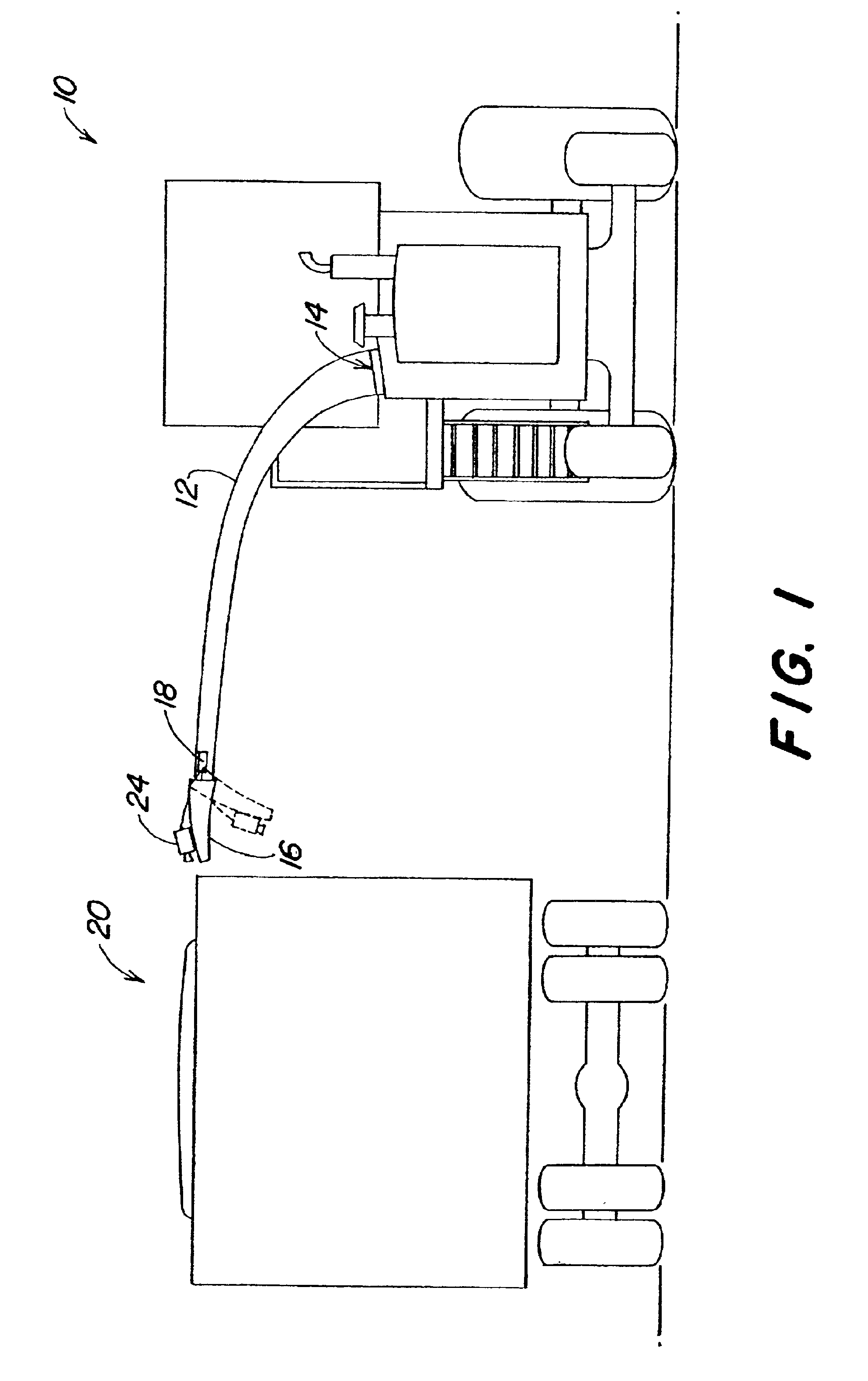
[0021]Referring to FIG. 1, a material collecting vehicle or crop gathering vehicle 10, such as a commercially available John Deere 50 Series self-propelled forage harvester, includes a pivotal crop discharge spout 12 which is pivoted by a conventional bi-directional electrohydraulic spout rotating motor 14. The spout 12 has a conventional cap 16 pivoted by a conventional cap motor 18.

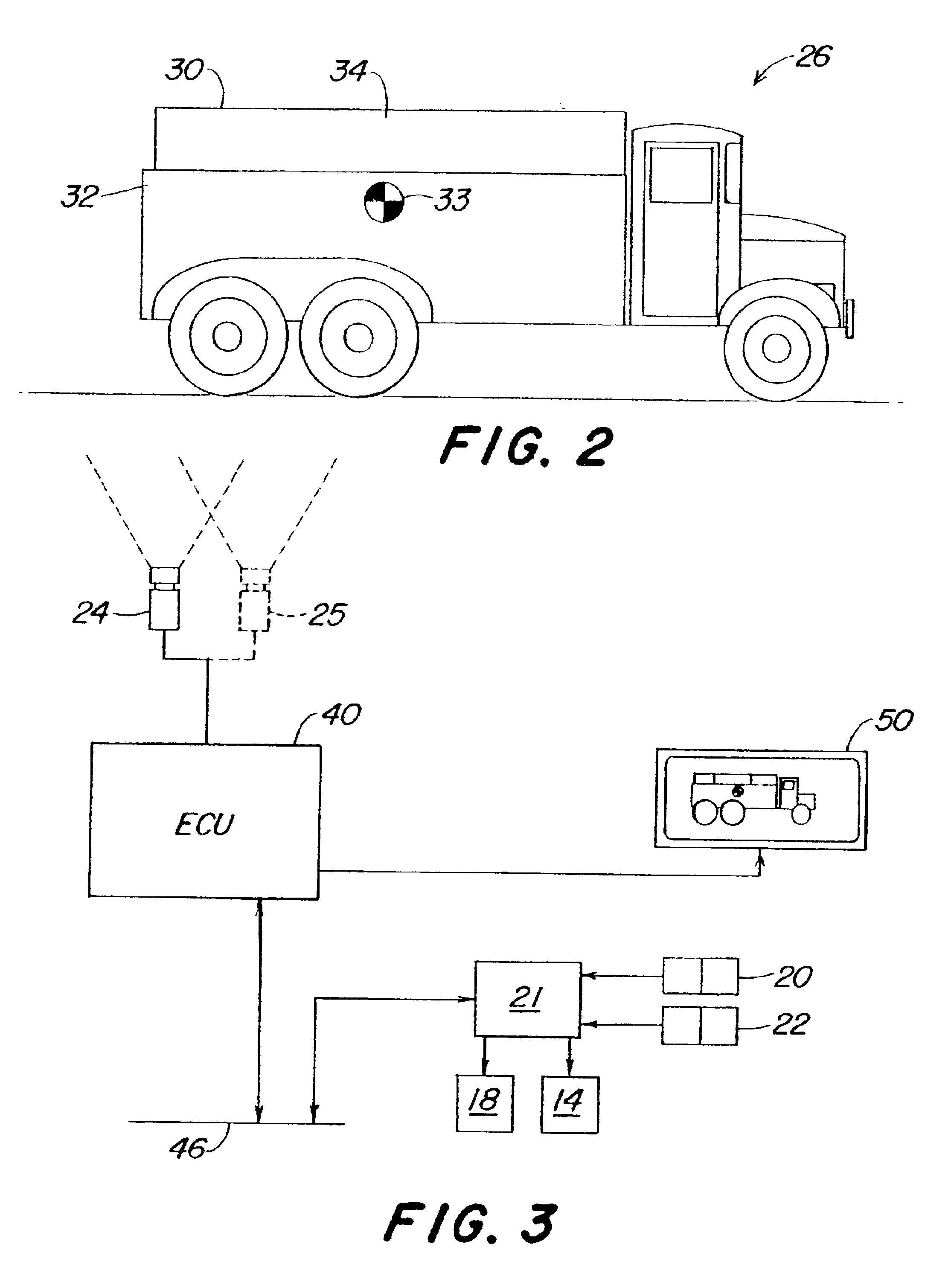
[0022]According to the present invention, a video camera 24 is mounted on or attached to the cap 16 at the end of the spout 12, so as to obtain an image of the field of view in the direction in which material is discharged from the spout 12 and of the crop receiving or hauling vehicle 26, which is shown from the side in FIG. 2. Optionally, as shown in FIG. 3, a second video camera 25 may also be mounted on the cap 16. Two cameras may be used to obtain a useable image in case the crop stream would occlude the view of a single camera. In this case, one camera would be mounted on each side of the crop stre...


PUM


Abstract

A spout control system controls and aims a spout and a spout cap of a crop harvesting vehicle with respect to a separate crop hauling vehicle moving with the harvesting vehicle. The control system includes a video camera which is mounted on the cap and which views a field of view which includes a portion of the hauling vehicle. An image signal generated by the camera is received by an image processing unit. The image processing unit processes a digitized form of the image signal and automatically generates spout and cap control signals as a function thereof. Actuators automatically aim the spout and the cap in response to the control signal.

Description

BACKGROUND OF THE INVENTION[0001]The invention relates to a spout control system for controlling and aiming the crop discharge spout and cap of a material collecting vehicle with respect to a separate material hauling vehicle moving with the collecting vehicle.[0002]It is difficult for the operator / driver of a material collecting vehicle, such as a forage harvester crop harvesting vehicle, to control the positioning of the crop discharge spout to achieve desired and / or even filling of a separate material hauling vehicle or crop hauling vehicle which moves along with the collecting or harvesting vehicle. This is because the operator must view spout and the hauling vehicle, thus diverting the operator's attention from other tasks which require the operator's attention.[0003]A system for monitoring loading of products from the spout of a harvester to a separate material hauling vehicle is described in German patent No. DE 44 26 059, published Jan. 2, 1996. This system includes a camera...

Claims


Application Information

Patent Timeline
IPC IPC(8): A01D43/073A01D43/00
CPCA01D43/073
Inventor ALEXIA, BARRY MICHAELBRISLEN, ANDREW JACKSONWICKING, JOHN RODERICFRANDSEN, JR., WALTER JAMES
Owner DEERE & CO
Why Eureka
Try Eureka