Hydrocyclone wear-detection sensor

a technology of wear detection sensor and hydrocyclone, which is applied in the direction of sealing, instruments, borehole/well accessories, etc., can solve the problems of failure of components and systems in which they operate, less desirable and/or unsuitable for other applications

Inactive Publication Date: 2005-09-20
KREBS ENGINEERS CORP +1
View PDF30 Cites 46 Cited by
  • Summary
  • Abstract
  • Description
  • Claims
  • Application Information

AI Technical Summary

Problems solved by technology

Hydrocyclones and other conduit components that are exposed to flowing substances are subject to abrasive wear which, if undetected, can lead to failure of the components and of the systems in which they operate.
While each of these techniques may have certain utility in specific applications, they also have limitations and disadvantages, such as leakage, which make them less desirable and / or unsuitable for other applications.

Method used


Image

  • Hydrocyclone wear-detection sensor
  • Hydrocyclone wear-detection sensor
  • Hydrocyclone wear-detection sensor

Examples


Embodiment Construction

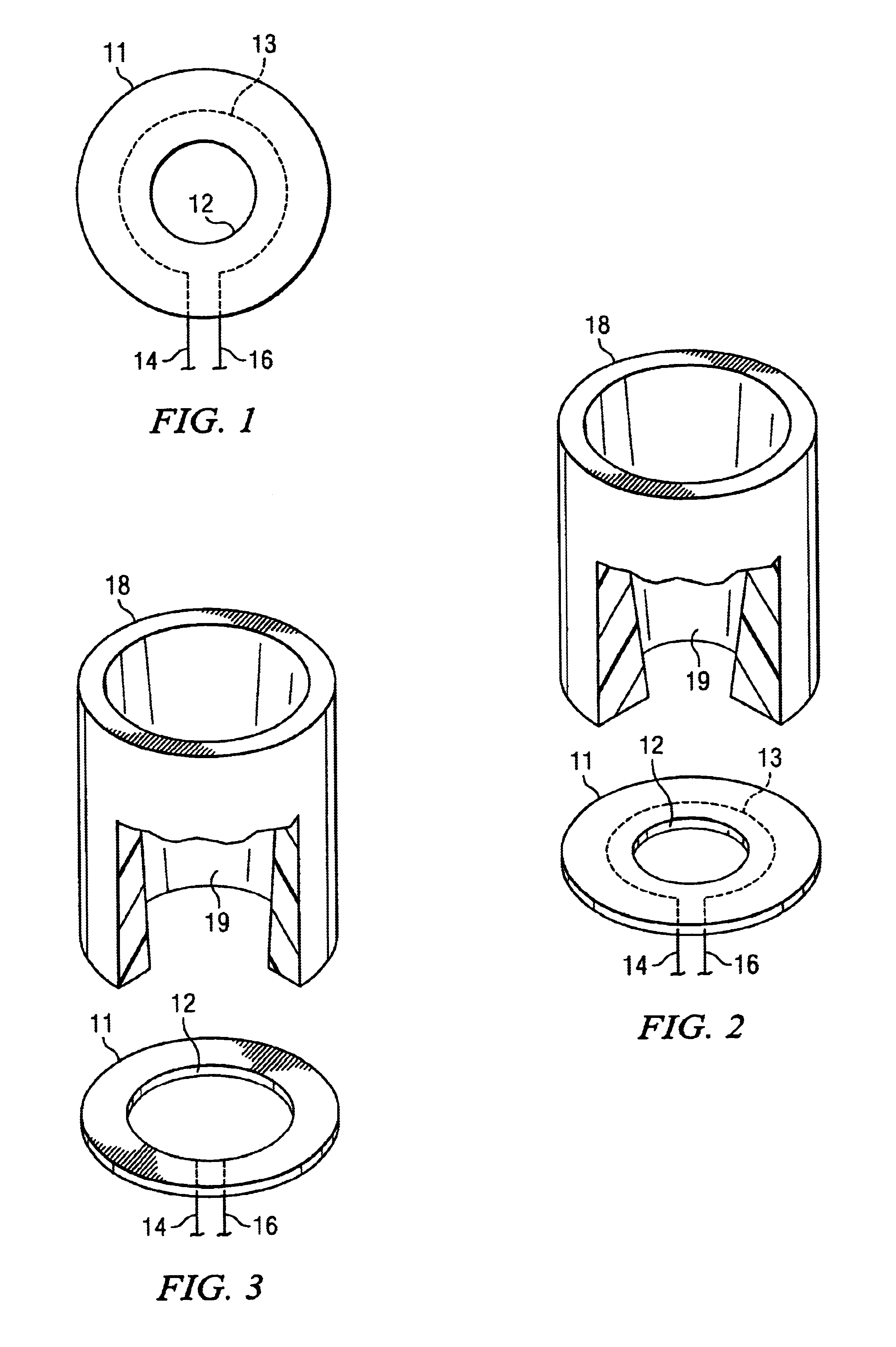
[0024]The heart of the invention lies in the idea of inserting a probe across the cross-section and through the inner wall of a conduit so as to expose it to the wear of flowable material. The probe incorporates preferably multiple spaced-apart conductors disposed at progressively greater distances from the inner wall of the conduit, thereby providing multiple sensors to detect wear as each conductor is worn away by the flowable material.

[0025]As used in this disclosure, the term “conduit” is intended to refer to any structure capable of sustaining fluid flow, in particular in the form of slurries, such as pipes, ducts, channels, and equipment like hydrocyclones. Therefore, while the description of the invention is based on hydrocyclone and pipe applications, its scope is not intended to be so limited.

[0026]In the most basic embodiment of the invention, illustrated in FIG. 1, the wear-detection sensor consists of a relatively thin annular body 11 of insulating material, such as uret...


PUM

PropertyMeasurementUnit
conductivityaaaaaaaaaa
insulatingaaaaaaaaaa
electrically conductiveaaaaaaaaaa

Abstract

Wear-detection sensor has a body of electrically insulating material with an opening through which a flowable substance can pass, and one or more electrical conductors surrounding the opening and adapted to undergo a discernable change in conductivity as the insulating material is worn away by the flowable substance.

Description

BACKGROUND OF THE INVENTION[0001]1. Field of the Invention[0002]This invention pertains generally to the detection of wear in hydrocyclones and other fluid-flow conduits that are exposed to abrasive substances and, more particularly, to a detection device that functions by monitoring wear on itself.[0003]2. Description of the Prior Art[0004]Hydrocyclones and other conduit components that are exposed to flowing substances are subject to abrasive wear which, if undetected, can lead to failure of the components and of the systems in which they operate.[0005]U.S. Pat. No. 5,024,755 discloses a hydrocyclone with tangential grooves in the outer wall of the separation chamber to create areas of reduced thickness that are designed to perforate and leak as the wall is worn away by the abrasive action of the liquid and particles in the chamber. Thus, the leakage is detected visually and the holes can be sealed with plugs until the chamber is replaced.[0006]U.S. Pat. No. 5,266,198 shows a some...

Claims


Application Information

Patent Timeline
Patent Type & Authority Patents(United States)
IPC IPC(8): B04C11/00G01N27/20G01N3/56
CPCB04C11/00G01N3/56G01N27/205Y10S277/919
Inventor OLSON, TIMOTHY
Owner KREBS ENGINEERS CORP
Why Eureka
Try Eureka