
Anti-shingling product conveying chain

a technology of conveying chain and product, which is applied in the direction of conveyors, transportation and packaging, etc., can solve the problems of shingling and damage to the top plate or chain, and achieve the effect of increasing the backward flexure of the conveying chain

Active Publication Date: 2005-09-20
REXNORD IND LLC
View PDF21 Cites 22 Cited by
  • Summary
  • Abstract
  • Description
  • Claims
  • Application Information

AI Technical Summary

Benefits of technology

[0006]The present invention provides a product conveying chain that inhibits shingling, and includes a top plate fixed to a base chain. The base chain is formed from a series of pairs of inner sidebars pivotally connected to adjacent pairs of outer sidebars. The top plate is fixed to the base chain, and has a trailing edge adjacent a following pair of sidebars. The trailing edge of the top plate includes at least one bump for engaging the following pair of sidebars to restrict articulation of the following pair of sidebars relative to the top plate compared to a top plate without the at least one bump. In one embodiment, the top plate includes a leading edge adjacent a preceding pair of sidebars. The leading edge includes at least one notch for receiving the preceding pair of sidebars to allow increased backward flexure of the conveying chain compared to a conveying chain having a top plate without the at least one notch.
[0007]A general objective of the present invention is to provide a conveying chain that is not susceptible to shingling. This objective is accomplished by providing bumps proximal the trailing edge of the top plate to restrict articulation of the following pair of sidebars relative to the top plate to inhibit shingling.
[0008]Another objective of the present invention is to provide an anti-shingling conveying chain without reducing the degree of backflexing of the conveying chain. This objective is accomplished by providing a top plate with a leading edge having at least one notch for receiving the preceding pair of sidebars to allow increased backward flexure of the conveying chain compared to a chain having a top plate without the at least one notch.

Problems solved by technology

Unfortunately, it is possible for the conveying chain to articulate in such a way that improperly positions the leading edge of the second top plate above the trailing edge of the preceding top plate to cause a condition called shingling.
Shingling forms an uneven conveying surface, and can damage the top plate or chain.

Method used


Image

  • Anti-shingling product conveying chain
  • Anti-shingling product conveying chain
  • Anti-shingling product conveying chain

Examples


Embodiment Construction

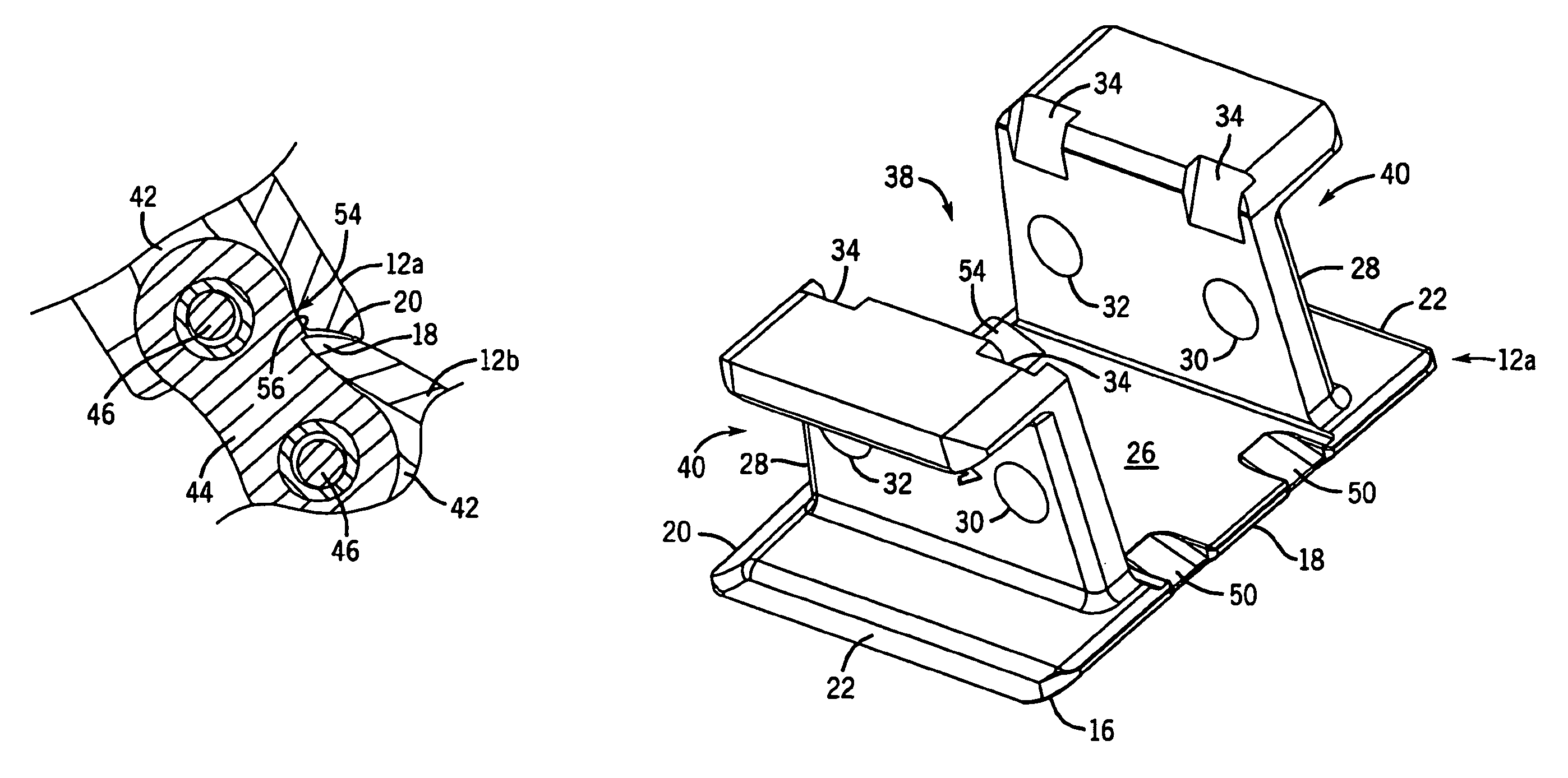
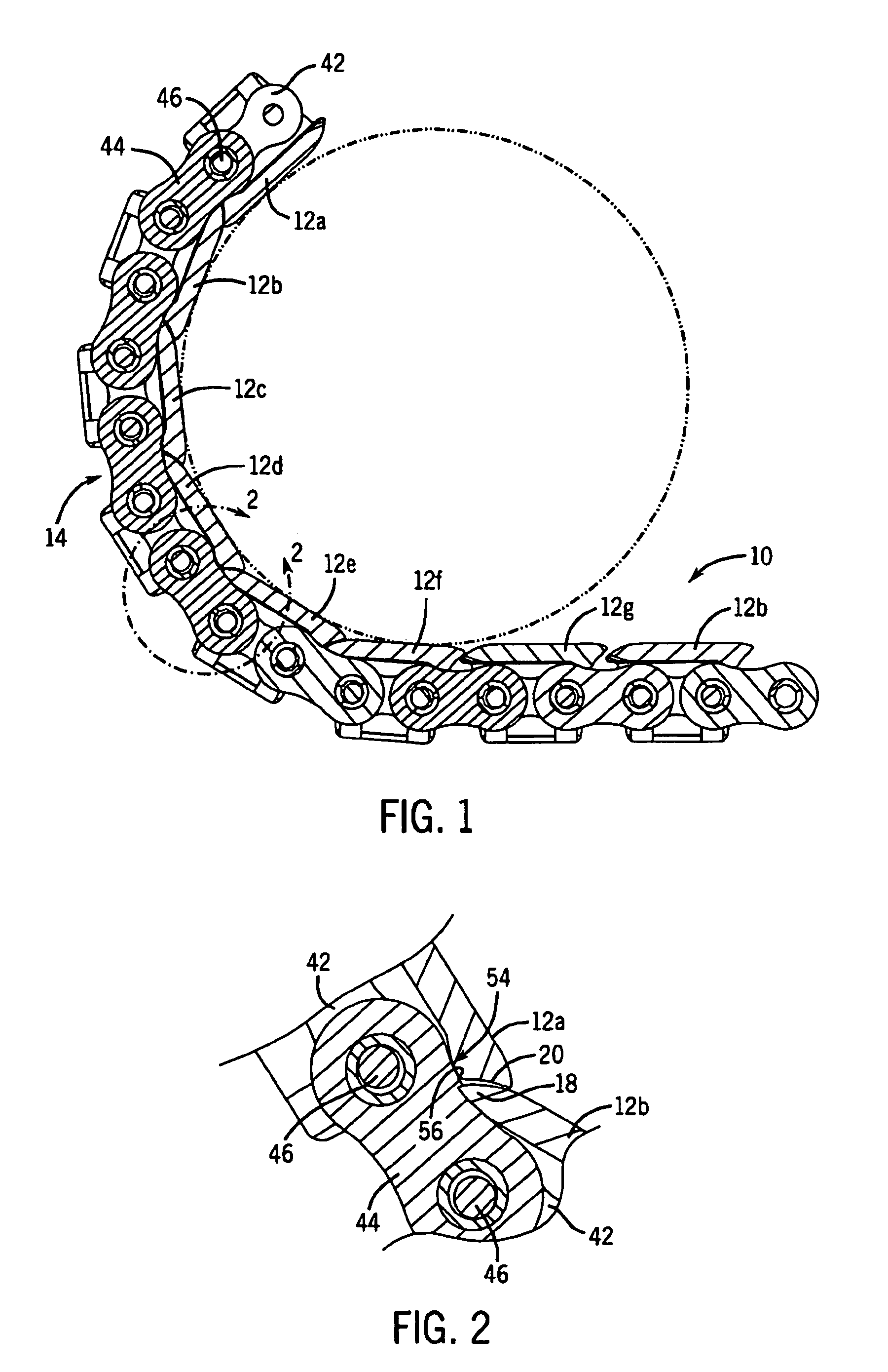
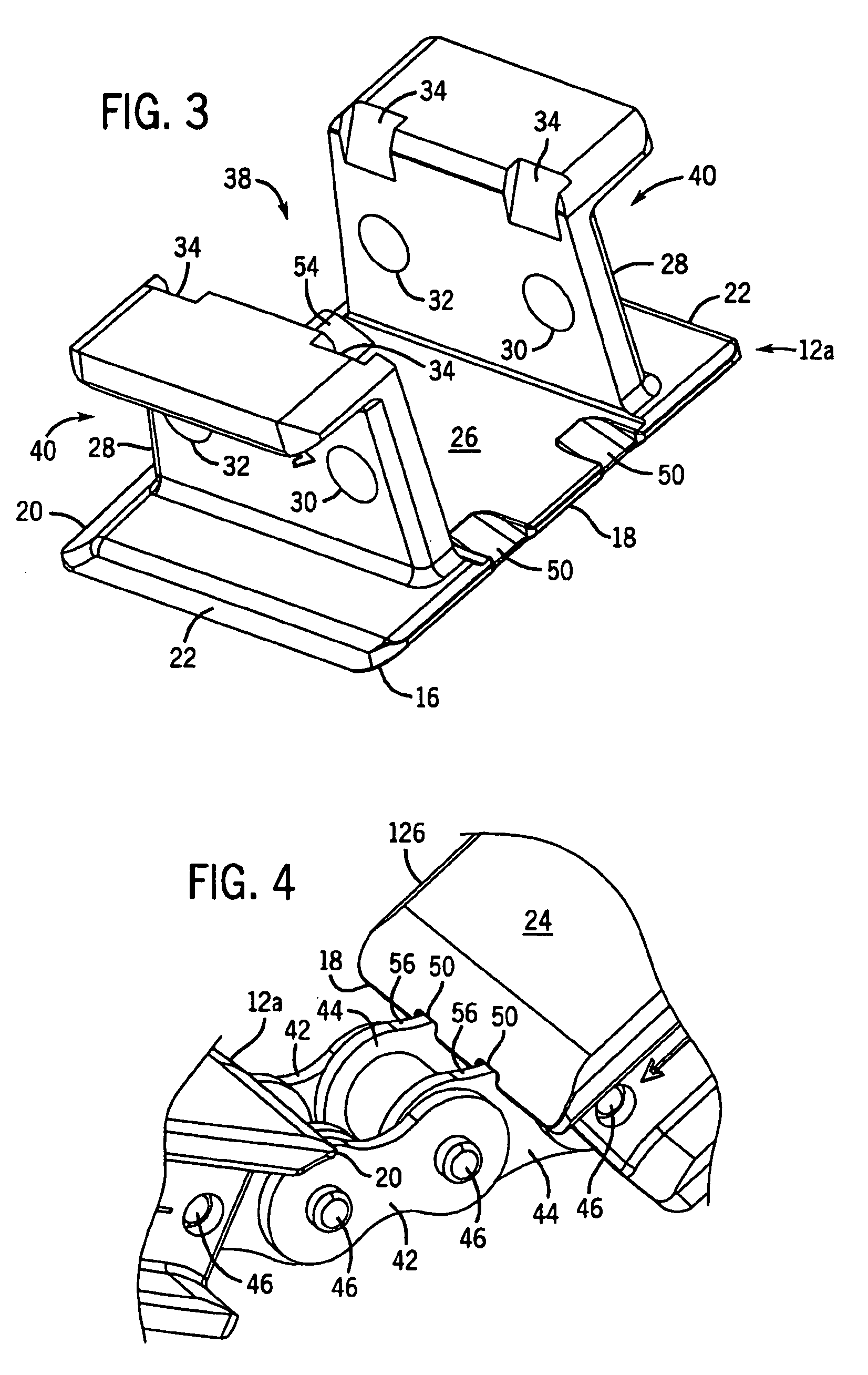
[0016]A product conveying chain 10, shown in FIGS. 1–6, includes a plurality of top plates 12a–h fixed to a base chain 14. The top plates 12a–h include notches 50 formed in their leading edges 18 that allow increased backflexing, and bumps 54 formed proximal their trailing edges 20 restrict articulation of the conveying chain 10 to prevent shingling. The combination of bumps 54 and notches 50 on each top plate 12a–h provides a conveying chain 10 that resists shingling while maintaining an acceptable degree of backflexing.

[0017]The base chain 14 includes pairs of outer sidebars 42 and pairs of inner sidebars 44 connected together by a plurality of chain pins 46. The inner sidebars 44 of the base chain 14 between adjacent top plates 12a, 12b join the outer sidebars 42 fixed to the preceding (upstream) top plate 12a and the outer sidebars 42 fixed to the following (downstream) top plate 12b. As a result, the inner sidebars 44 are the following inner sidebars 44 for the upstream top pla...


PUM


Abstract

A product conveying chain includes a top plate fixed to a base chain. The base chain is formed from a series of pairs of inner sidebars pivotally connected to adjacent pairs of outer sidebars. The top plate is fixed to the base chain, and has a trailing edge adjacent a following pair of sidebars. The trailing edge of the top plate includes at least one bump for engaging the following pair sidebars to restrict articulation of the following pair of sidebars relative to the top plate compared to a top plate without the at least one bump. In one embodiment, the top plate includes a leading edge adjacent a preceding pair of sidebars. The leading edge includes at least one notch for receiving the preceding pair of sidebars to allow increased backward flexure of the conveying chain compared to a conveying chain having a top plate without the at least one notch.

Description

CROSS REFERENCES TO RELATED APPLICATIONS[0001]Not ApplicableSTATEMENT REGARDING FEDERALLY SPONSORED RESEARCH[0002]Not ApplicableTECHNICAL FIELD[0003]The present invention relates to conveying chains, and more particularly to back-flexing product conveying chains having a top plate for carrying objects.DESCRIPTION OF THE BACKGROUND ART[0004]Product conveying chains typically include a base chain having inner sidebars pivotally linking outer sidebars. A top plate is fixed to the base chain, and provides a surface for conveying a product. These conveying chains must be able to articulate in order to negotiate drive and idler sprockets. Since the base chain joints must be free to articulate, the top plates are typically affixed to each outer sidebar. The inner sidebar is free to articulate relative to the top plate allowing flexure of the assembly. The degree of back flexure is restricted to the point where the leading edge of the top plate contacts the edges of the adjacent inner sideb...

Claims


Application Information

Patent Timeline
Patent Type & Authority Patents(United States)
IPC IPC(8): B65G17/06
CPCB65G17/065
Inventor SCHUMACHER, JEFFREY A.
Owner REXNORD IND LLC
Learn More