
Vehicle air suspension

a technology of air suspension and pinion shaft, which is applied in the direction of suspension arms, pivoted suspension arms, transportation and packaging, etc., can solve the problems of occupant discomfort, parallel pinion arrangement and broken back arrangement of pinion shafts are susceptible to change in pinion shaft angle, and achieve the effect of relieving the axle of forces

Inactive Publication Date: 2012-06-28
SUBBARAYALU GOWTHAMAN +1
View PDF33 Cites 4 Cited by
  • Summary
  • Abstract
  • Description
  • Claims
  • Application Information

AI Technical Summary

Benefits of technology

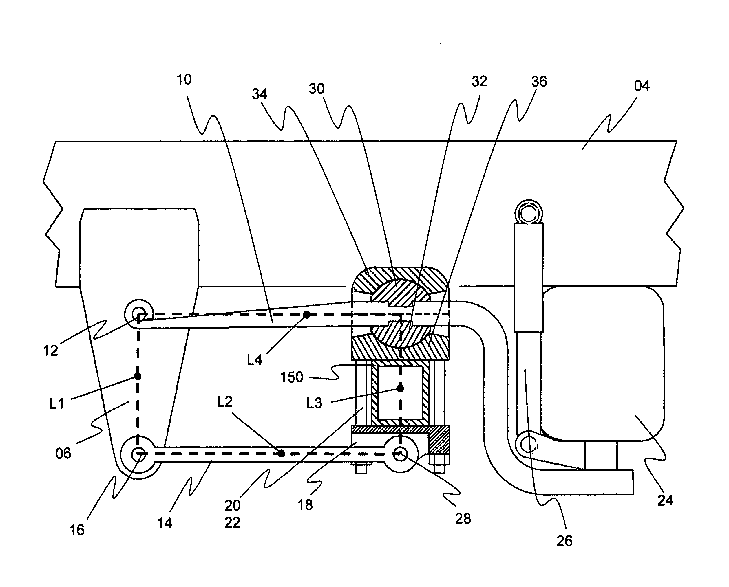
[0012]The invention is a vehicle trailing arm air suspension system and more particularly a truck driven-axle air suspension system. One of the preferred embodiment of this invention is based on four bar mechanism, the four bars represented by 1) hanger bracket, 2) trailing arm of preferably spring steel and preferably rectangular cross section, 3) link rod and 4) driven axle housing with its attachments. The invention as applied to a single driven axle comprises a pair of trailing arm assemblies. Each assembly comprises a hanger bracket, a trailing arm and its attachments to hanger bracket and axle, a link rod and its attachments to hanger bracket and axle, an air spring and shock absorber. Front end of the trailing arm is pivotally connected to upper portion of hanger bracket. The hanger bracket is rigidly attached to the frame rail. The middle portion of the trailing arm is “spherically” connected to top of driven-axle by two concentric spherical segments one below and one above the trailing arm. The spherical segments are suitably keyed to the trailing arm to prevent linear relative movements between the segments and the trailing arm. The spherical segments are preferably fastened together on either sides of the trailing arm. The said spherical segments are contained and slide inside matching spherical cavities formed in blocks above and below trailing arm. The said blocks together are rigidly attached to top of the axle by clamping them to the axle preferably using U-shaped bolts. All four spherical surfaces have a common center. Required clearance is maintained between the spherical cavities in the blocks and the spherical segments to allow free sliding of the spherical surfaces of segments on the matching spherical surfaces of blocks. The spherical segments combined with spherical cavities in the blocks form a limited articulation spherical joint. The center of the joint thus formed by the spherical surfaces of segments and blocks act as one of four nodes of four bar mechanism. The pivoted connection of the front end of the trailing arm acts as one of four nodes. The portion of the trailing arm, rear of axle, is connected to the bottom of an air spring and to bottom of a shock absorber. Other end of the air spring and the shock absorber are connected to the main frame rail. One end of the link rod is pivotally connected to the lower portion of hanger bracket and other end is pivotally connected to the lower portion of the axle to form one of the links of four bar mechanism. In operation, the hanger bracket acts as the ‘ground link’ of the four bar mechanism and driven axle, with its connections to trailing arm and link rod, acts as the ‘driven link’ of four bar mechanism. This arrangement of four bar mechanism thus formed is geometrically arranged to achieve the required ideal design angle of the pinion shaft. The lengths of opposite links are preferably maintained equal to achieve substantially constant pinion shaft angle during jounce and rebound motion of axle. This arrangement of four bar mechanism makes the suspension substantially non-reactive to traction force reaction and brake torque reaction on axle. Drive torque and brake torque induced reaction on axle, about axle axis, are substantially countered by the front portion of the trailing arm and the bottom link rod. To control the lateral motion of the axle during jounce and rebound, one end of a tie rod is pivotally or spherically attached to the frame rail and the other end of the tie rod is pivotally or spherically attached to the axle. The vertically resilient front portion of the trailing arm and the air spring in the rear portion of trailing arm act as energy absorption elements of the suspension. Though the preferred embodiment of this invention has a vertically resilient front portion of the trailing arm, it can also be a non-resilient trailing arm. The spherical joint on top of the axle substantially relieves the axle of forces that may otherwise strain the axle if the trailing arm is rigidly attached to axle, more particularly during cross articulation when the wheels on either side of the axle are not in same horizontal plane.

Problems solved by technology

While it is a industry practice to set the pinion angle to its ideal design angle that cancels the joint-working-angle of all the cardan joints in the driveline system, a ‘rigidly axle mounted trailing arm set up’ generally does not maintain the pinion shaft angle during jounce and rebound of axle and during acceleration and braking.
Both parallel pinion arrangement and broken back arrangement of the pinion shafts are susceptible to change in pinion shaft angle from their ideal design angle.
Effect of this change is higher torsional and inertial vibrations emanating from the inter axle shaft joints of both axles causing occupant discomfort and cumulative structural damage to the driveline parts.
However, pinion shaft angle change during jounce and rebound still exist in these “rigidly” axle mounted air suspensions.
With higher torque output of current generation engines and higher braking performance demands for similar applications, maintaining the pinion shaft angles close to their ideal design angle during vehicle operation has become more challenging with prior art “rigidly” axle mounted trailing arm air suspensions.

Method used


Image

  • Vehicle air suspension
  • Vehicle air suspension
  • Vehicle air suspension

Examples


Embodiment Construction

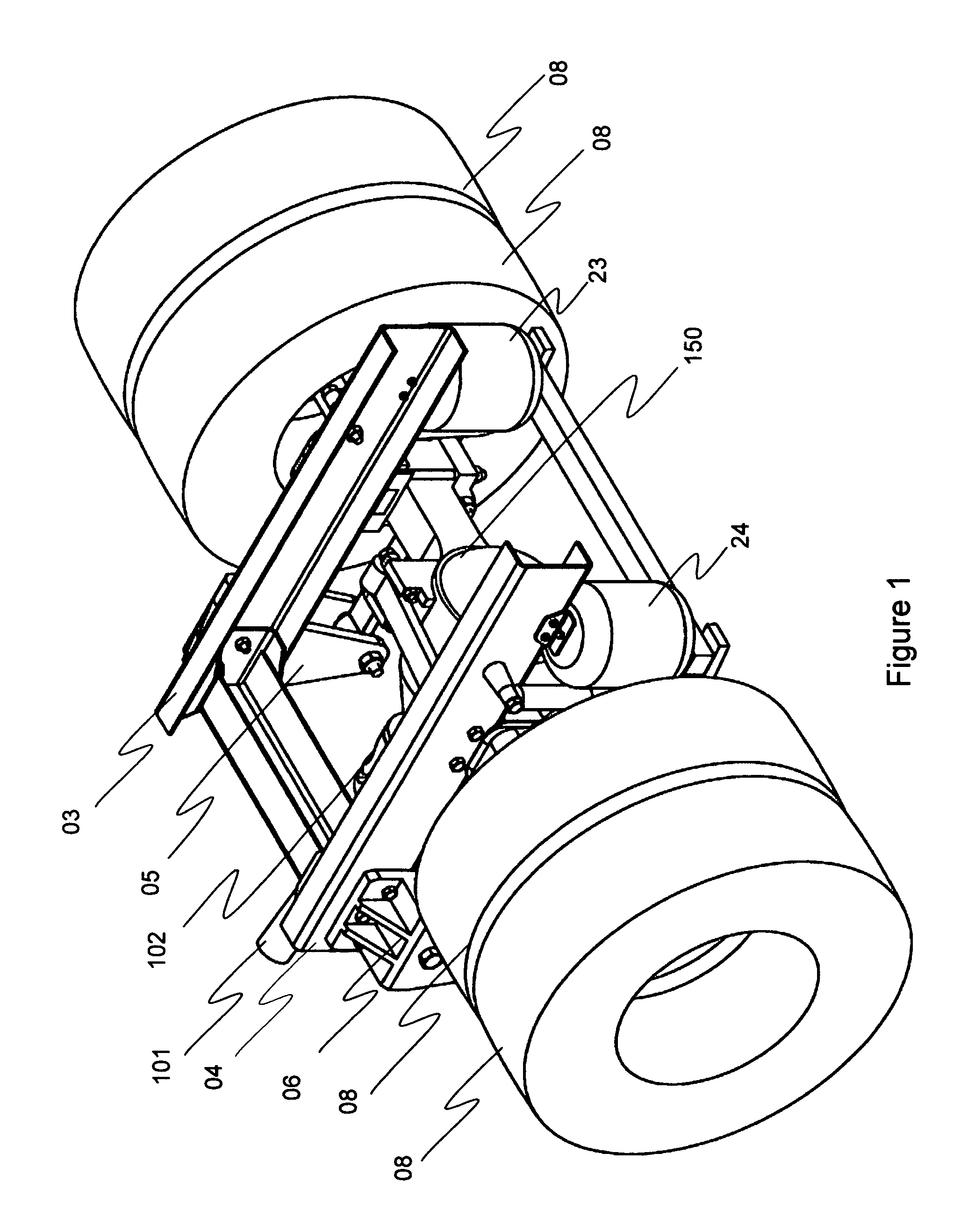
[0022]FIG. 1 illustrates portion of the truck chassis showing the general arrangement of the suspension on a single driven axle with the propeller shaft 101 and axle 150. Frame rails 03 and 04 are oppositely spaced steel channel sections oriented longitudinally in the truck. Hanger brackets 05 and 06 are shown mounted on the out-board side of the frame rails. Tires 08 are shown mounted on either side of the axle 150. Partial view of propeller shaft 101 is shown connected by cardan type universal joint 102 to a driven axle 150.

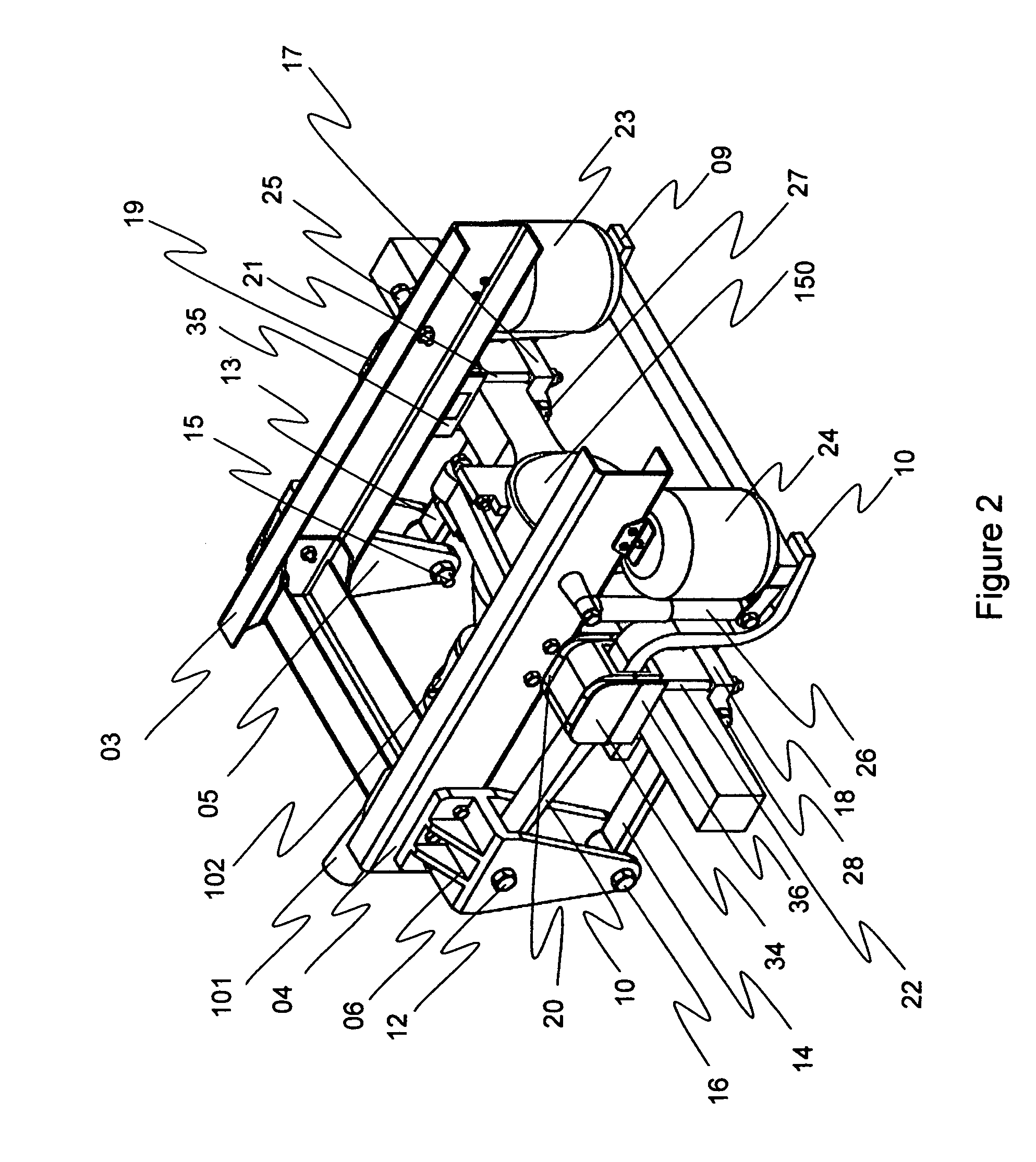
[0023]FIG. 2 illustrates portion of truck chassis showing general arrangement of the suspension on a single driven axle without tires. The hanger brackets 05 and 06 are rigidly attached to the frame rails 03 and 04 respectively by a plurality of fasteners. Trailing arms 09 and 10 are shown connected to the upper portion of the hanger brackets 05 and 06 by pivot pins 11 (not visible in the Figure) and 12 respectively. The portion of the trailing arms 09 and 10 a...


PUM


Abstract

The invention is an air suspension system on vehicle driven axle to maintain substantially constant pinion shaft angle in response to traction force reaction on axle and brake torque induced reaction on axle and in response to position of axle in jounce and rebound. The invention is based on four bar mechanism geometrically arranged to achieve substantially constant pinion shaft angle. The four bars are represented by 1) hanger bracket, 2) trailing arm, 3) link rod and 4) driven axle housing with its attachments. In one of the preferred embodiments, the trailing arm is pivotally connected to top portion of hanger bracket attached to frame rail. The middle portion of trailing arm is “spherically” connected to axle top. Rear portion of trailing arm is connected to frame rail by air spring and shock absorber. One end of said link rod is pivotally connected to lower portion of hanger bracket and other end is pivotally connected to lower portion of axle.

Description

BACKGROUND OF THE INVENTION[0001]1) Field of the Invention[0002]This invention relates to vehicle trailing arm air suspension system, more particularly to a driven axle and more relevant to tandem driven axles. Driven axles of trucks carry invariably an input shaft also called pinion shaft to which is connected a propeller shaft to transmit power from engine to the differential assembly from where power is distributed to the wheels. A cardan type universal joint generally joins the propeller shaft and pinion shaft in the driven axle. Angle of pinion shaft is set in a truck to achieve low included angle between the propeller shaft and pinion shaft. Low included angle between the propeller shaft and the pinion shaft will induce low torsional acceleration of the pinion shaft which is desirable. Maintaining the pinion shaft angle around its set design angle in various positions of the axle travel during jounce and rebound is a challenge in a trailing arm air suspension. Change in the pi...

Claims


Application Information

Patent Timeline
Patent Type & Authority Applications(United States)
IPC IPC(8): B60G7/00
CPCB60G9/00B60G2200/314B60G11/27B60G2300/02B60G2300/04B60G2204/4308
Inventor SUBBARAYALU, GOWTHAMANSUBBARAYALU, RAJAKUMAR
Owner SUBBARAYALU GOWTHAMAN
Learn More