Seal retainer

a technology of sealer and sealer, which is applied in the direction of fluid pressure seal joints, cable terminations, mechanical equipment, etc., can solve the problems of large system footprint, difficult to change components, and heat affected areas that are prone to corrosion and particle generation, and achieve the effect of improving performance and handling characteristics

Inactive Publication Date: 2005-09-20
GARLOCK SEALING TECHNOLOGIES
View PDF26 Cites 55 Cited by
  • Summary
  • Abstract
  • Description
  • Claims
  • Application Information

AI Technical Summary

Benefits of technology

[0013]The various aspects of the present invention provide a seal and retainer with improved performance and handling characteristics. While the seal and retainer of the present invention may be used in many different sealing applications, they are particularly well suited for high vacuum, low particulate environments such as MSM gas delivery systems.

Problems solved by technology

These systems require a large footprint.
It is also difficult to change components since they are welded together.
Additionally, the weld creates a heat affected area that is prone to corrosion and particle generation.
The complexity of seals of this nature may introduce manufacturing inconsistencies that result in reduced performance.
One disadvantage to this design is the propensity for seals to fall out when the retainer is distorted or flexed.
Retainers of this design do not provide the positive retention required of such systems.

Method used


Image

  • Seal retainer
  • Seal retainer
  • Seal retainer

Examples


example

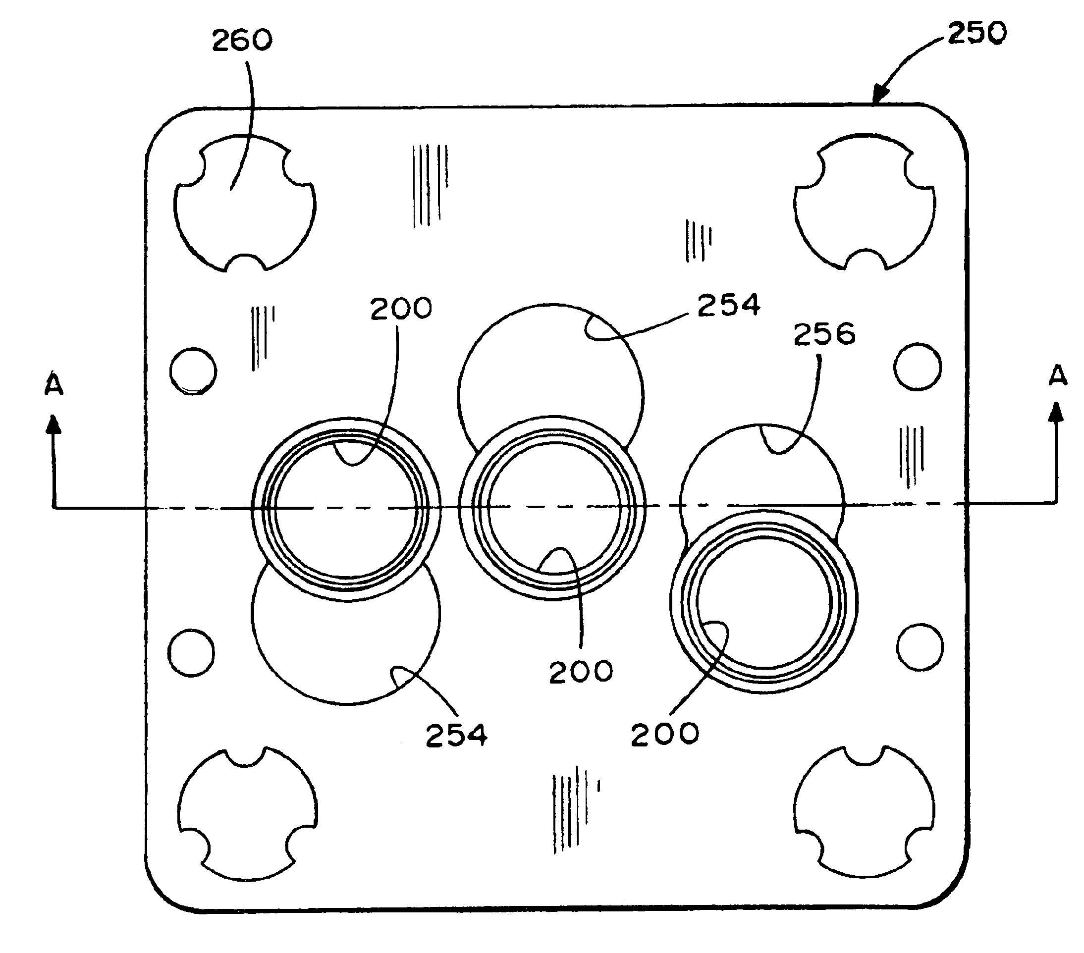
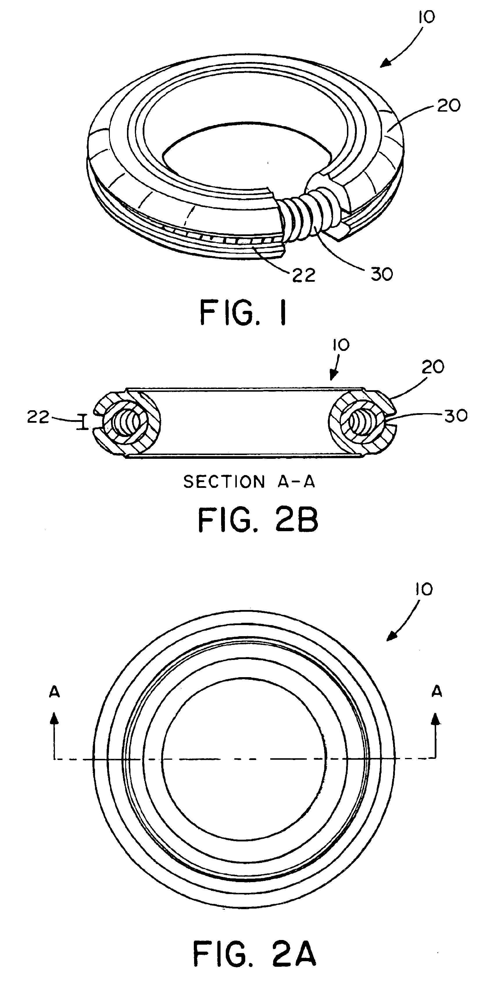
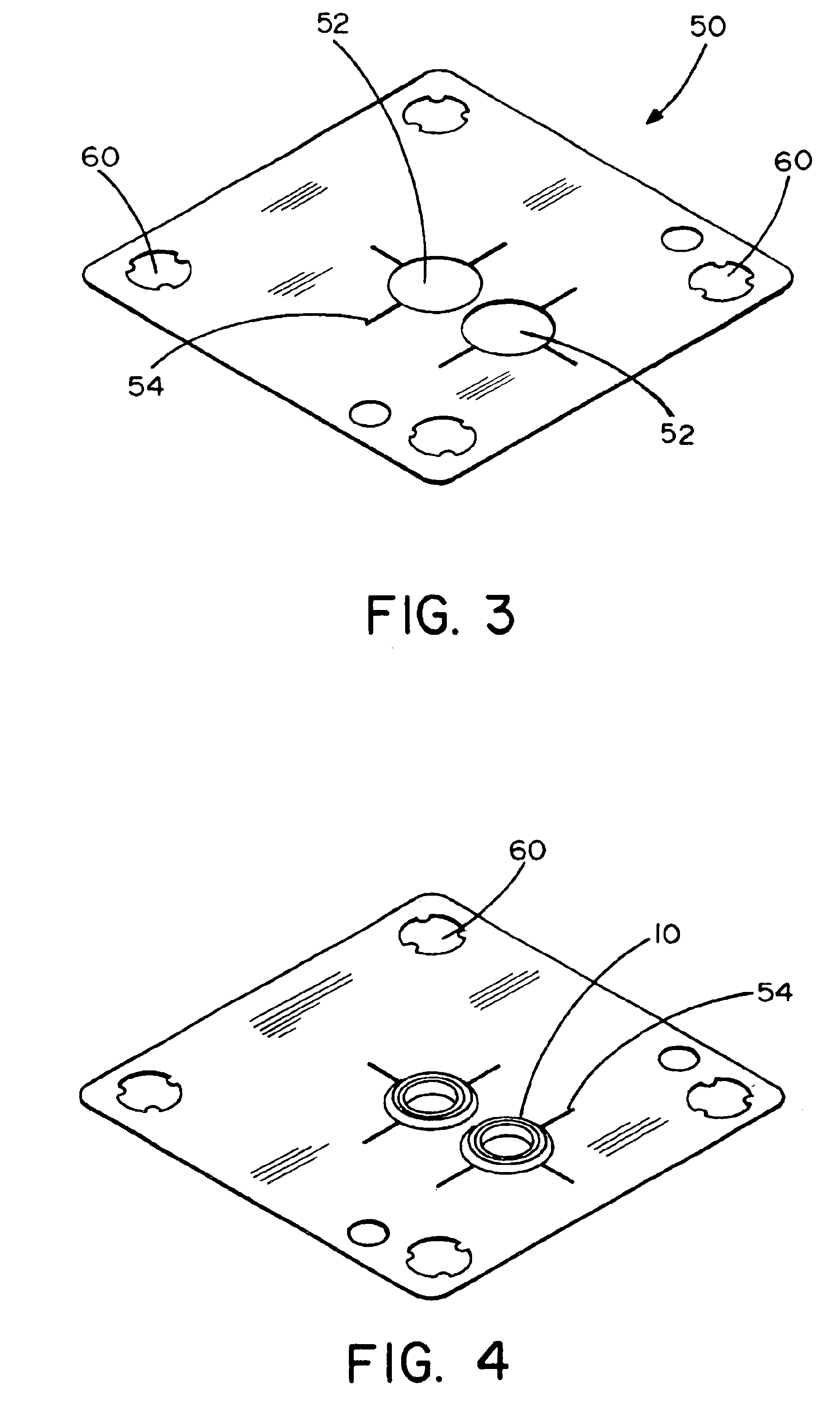
[0043]The following is an example of a seal and retainer for use in MSM gas delivery systems. The identifying numbers refer to those described above and viewed in FIGS. 4 through 11. The dimensions are provided to give the reader perspective as to relative size and scale and are by no means meant to limit the scope of the invention.

[0044]In an exemplary embodiment of the present invention, the seal 100, 200 is dimensioned to fit a standard MSM gas delivery assembly. The seal comprises an inner diameter of about 0.188 inches. The outer diameter of the seal comprises about 0.275 inches, and the axial height of the seal is about 0.063 inches. The outer peripheral groove is designed to fit the inner diameter of a seal retaining aperture in a seal retainer. Thus, the apex of the arch portion extends about 0.0175 inches from the radially outer end of the seal and the peripheral groove is about 0.038 inches high at the radially outer end of the seal.

[0045]The axially outer sides of the sea...


PUM


Abstract

The present invention relates to a seal comprising an annular sealing body comprising a radially outer peripheral groove, an upper load concentrating projection, a lower load concentrating projection, a compression relief region extending from the center of the load concentrating projections to the radially inner edge of the seal, and a compression relief region extending from the center of the load concentrating projections to the radially outer edge of the seal. Additionally, aspects of the present invention relate to a seal retainer comprising a thin metal sheet comprising a seal retaining aperture comprising a reception lobe and a retention lobe; wherein the reception lobe has a diameter larger than the outer diameter of the seal to be retained therein, and the seal retaining aperture has a diameter larger than the minimum diameter of the arch portion of the outer peripheral groove.

Description

CROSS REFERENCE TO RELATED APPLICATIONS[0001]This application claims priority to U.S. Provisional Patent Application Ser. No. 60 / 358,316 filed Feb. 20, 2002, the disclosure of which is herein incorporated by reference.FIELD OF THE INVENTION[0002]The present invention relates to a sealing assembly, and more particularly, to an elastically deformable metallic seal with a plastically deformable load concentration feature and a retainer plate for carrying one or more metallic seals.BACKGROUND OF THE RELATED ART[0003]Traditional semiconductor manufacturing gas delivery systems consist of components that are welded together with stainless steel tubing. These systems require a large footprint. It is also difficult to change components since they are welded together. Additionally, the weld creates a heat affected area that is prone to corrosion and particle generation.[0004]The new Modular Surface Mount (MSM) technology allows for a much smaller footprint. The components are instead bolted ...

Claims


Application Information

Patent Timeline
Patent Type & Authority Patents(United States)
IPC IPC(8): F16J15/06F16J15/08
CPCF16J15/061F16J15/0887F16J15/08F16J15/06
Inventor WHITLOW, MARK S.HARR, JOHN S.MCCALL, RYAN D.
Owner GARLOCK SEALING TECHNOLOGIES
Why Eureka
Try Eureka