Drawer slide adjustment mechanism

a technology of adjustment mechanism and drawer slide, which is applied in the direction of drawers, furniture parts, domestic applications, etc., can solve the problems of drawer slide misalignment and difficulty in proper installation of drawer slid

Inactive Publication Date: 2005-09-20
STANDARD PURISHIJIYAN
View PDF22 Cites 60 Cited by
  • Summary
  • Abstract
  • Description
  • Claims
  • Application Information

AI Technical Summary

Problems solved by technology

At times, proper installation of drawer slides may be difficult.
With a drawer fixedly attached to a drawer slide, and the drawer slide fixedly attached to a cabinet, misalignment of the drawer slide may result in the drawer being misaligned with the cabinet.

Method used


Image

  • Drawer slide adjustment mechanism
  • Drawer slide adjustment mechanism
  • Drawer slide adjustment mechanism

Examples


Embodiment Construction

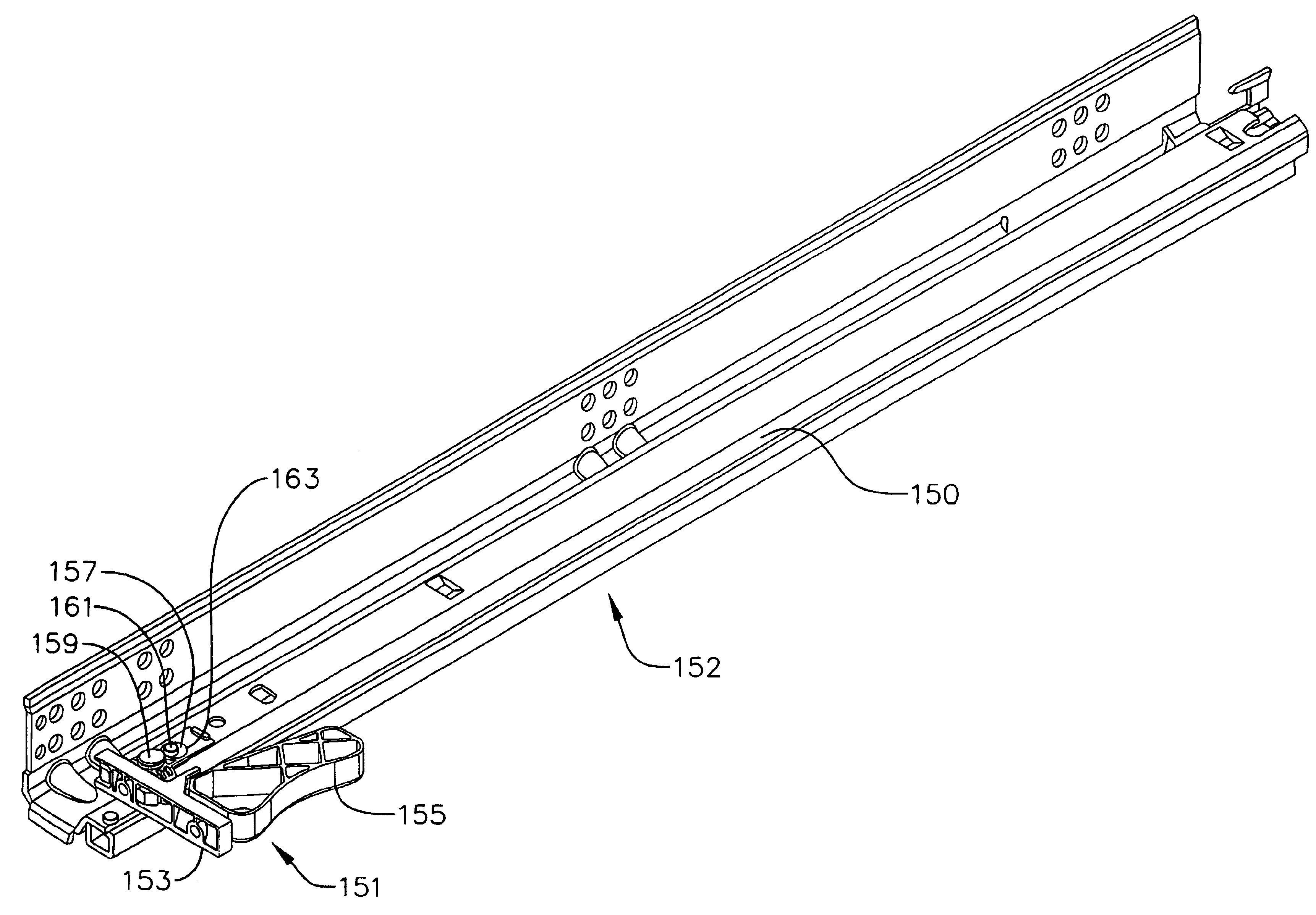
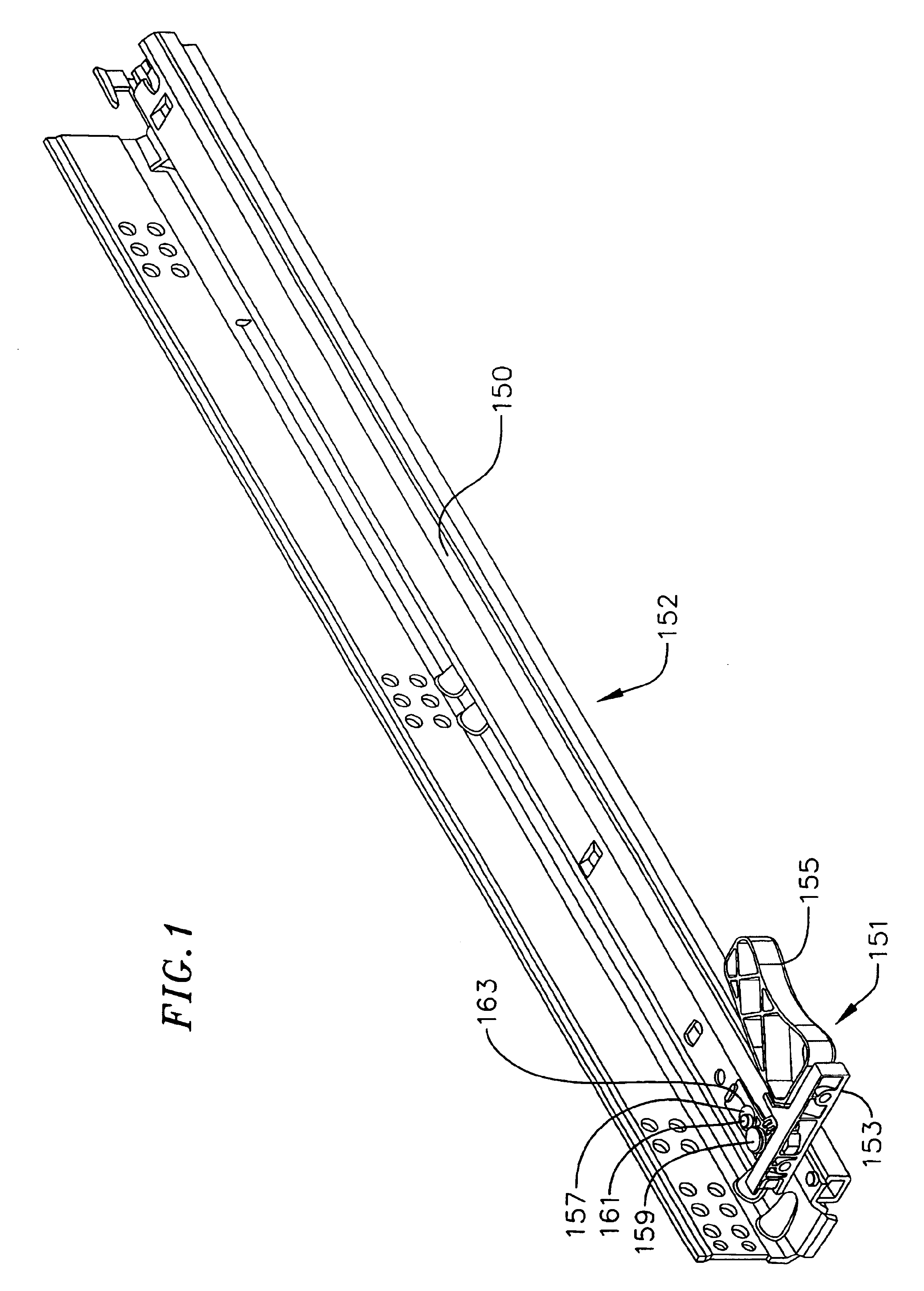
[0014]FIG. 1 illustrates an undermount drawer slide 152 and position adjustment mechanism 151. The undermount drawer slide is generally positioned underneath a drawer (not shown). The position adjustment mechanism is placed at a front of a shelf rail 150, and includes a mounting bar 153 with a handle 155 and a positioning element 157. The positioning element is inserted within the outline formed by the shelf rail, with the handle extending parallel to the shelf rail. The mounting bar is coupled to a backside of a front of the drawer.

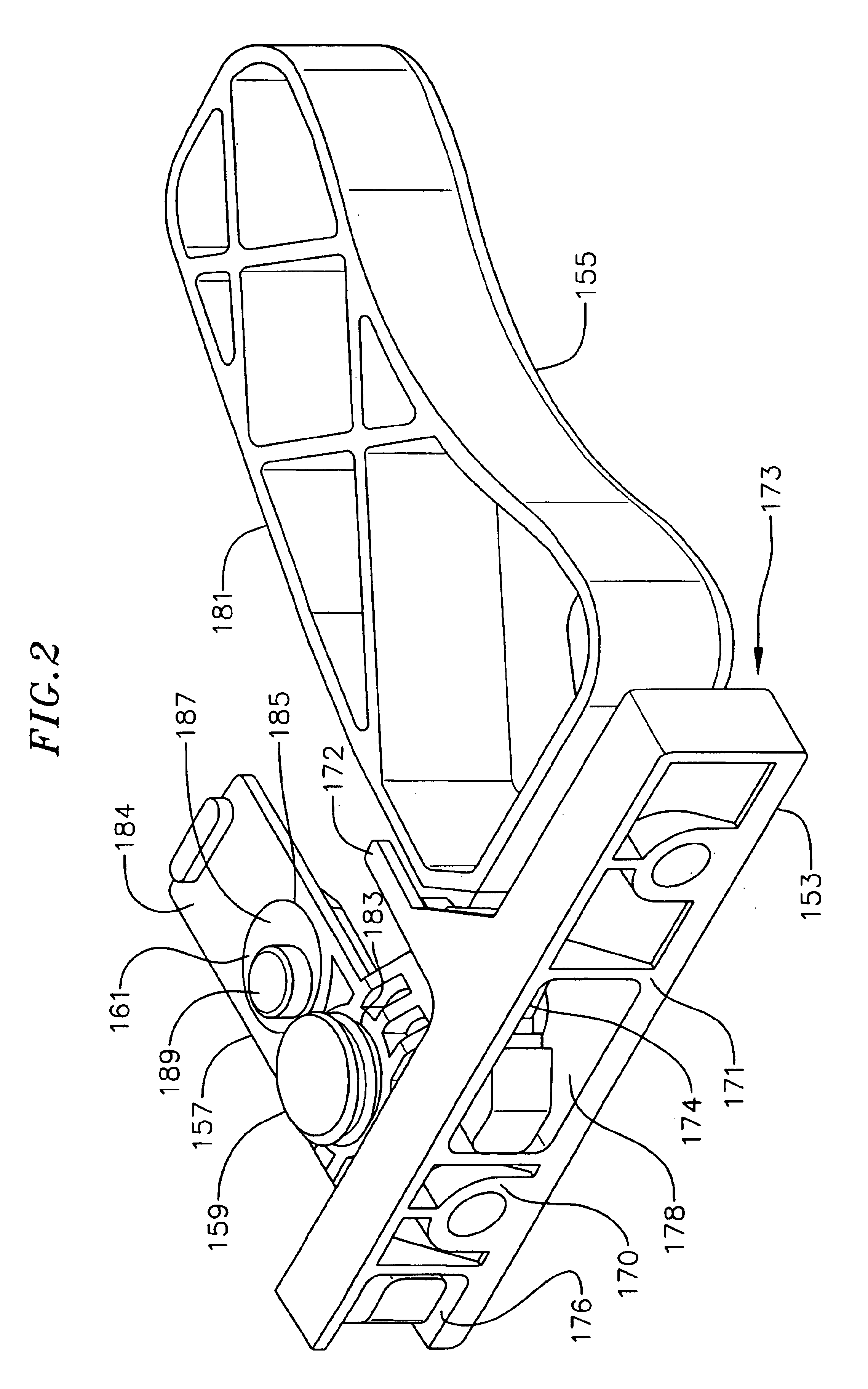
[0015]The positioning element includes a vertical positioning element 159 and a horizontal positioning 161 element, each extending through a cutout 163 of a web of the shelf rail. The vertical positioning element is movable, or translatable vertically within the cutout, it being understood that vertical and other directional terms being used with reference to a positioning element mounted with an undermount drawer slide. With the reference system so indi...


PUM


Abstract

A drawer slide positioning mechanism providing two directional adjustment of a drawer with respect to a drawer slide. The positioning mechanism fits within an outline of a rail of a drawer slide. The positioning mechanism includes a vertical adjustment element and a horizontal adjustment element.

Description

BACKGROUND OF THE INVENTION[0001]The present invention relates generally to drawer slide adjustment mechanisms, and more particularly to a vertical and horizontal drawer slide adjustment mechanism.[0002]Drawer slides are ubiquitous in extendably coupling cabinets with drawers, shelves, and the like. The drawer slides allow a drawer, for example, to be extended from a cabinet to provide easy access to the contents of the drawer. Drawer slides are also used in a number of other applications, including rack-mounted applications or whenever mounting of an item in an extendible manner is desired.[0003]Drawer slides often have a first rail coupled to a cabinet and a second rail coupled to a drawer. The second rail generally is extendable from the first rail. In addition, some drawer slides may have an intermediate rail coupling the first rail and the second rail, forming a three rail drawer slide.[0004]At times, proper installation of drawer slides may be difficult. With a drawer fixedly ...

Claims


Application Information

Patent Timeline
Patent Type & Authority Patents(United States)
IPC IPC(8): A47B88/04A47B88/49
CPCA47B88/0422A47B88/427
Inventor KIM, DANIELLE, BAOLOC
Owner STANDARD PURISHIJIYAN
Why Eureka
Try Eureka