A method and a device for extract that center of a laser stripe of a rail profile unde a dynamic driving environment

A laser stripe and driving environment technology, applied in the field of data processing, can solve problems such as uneven image brightness, laser missing, laser contour deformation, etc., to achieve the effect of avoiding template matching, ensuring accuracy, and enhancing robustness

Active Publication Date: 2019-02-26
RAILWAY INFRASTRUCTURE TESTING RES INST CHINA ACAD OF RAILWAY SCI +2
View PDF3 Cites 16 Cited by
  • Summary
  • Abstract
  • Description
  • Claims
  • Application Information

AI Technical Summary

Problems solved by technology

One of the main problems is that the current laser stripe extraction method is sensitive to noise and illumination changes, and in the actual driving environment of the train, the interference information introduced by illumination changes, uneven reflection and surface unevenness is reflected in the laser image in the form of noise. above, these interfering factors will change the profile shape of the laser
The traditional light strip center extraction method mainly improves the accuracy of laser detection at the expense of robustness. This type of method is often suitable for indoor detection scenarios with controllable ambient light and laser power. However, due to various noises in the outdoor driving environment interference, resulting in deformation of the laser profile, uneven brightness of the image, and even complete loss of part of the laser, so the traditional method is not suitable for railway scenarios
[0004] For the above problems, no effective solution has been proposed

Method used

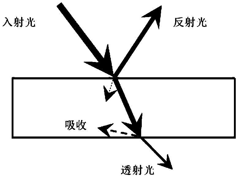

Image

  • A method and a device for extract that center of a laser stripe of a rail profile unde a dynamic driving environment
  • A method and a device for extract that center of a laser stripe of a rail profile unde a dynamic driving environment
  • A method and a device for extract that center of a laser stripe of a rail profile unde a dynamic driving environment

Examples


Embodiment Construction

[0039] The following will clearly and completely describe the technical solutions in the embodiments of the present invention with reference to the accompanying drawings in the embodiments of the present invention. Obviously, the described embodiments are only some of the embodiments of the present invention, not all of them. Based on the embodiments of the present invention, all other embodiments obtained by persons of ordinary skill in the art without making creative efforts belong to the protection scope of the present invention.

[0040]The inventors found that in line structured light measurement, the degree of stripe deformation reflects the depth of the measured object, so the accurate detection of the center position of the structured light deformed stripe is one of the key issues affecting the accuracy of the structured light system. It is worth pointing out that the determination of the center position of the structured light stripe in the structured light system is d...


PUM


Abstract

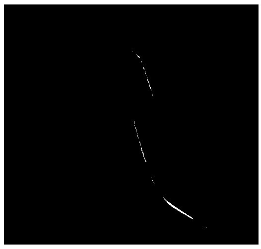
A method and device for extract laser stripe cent of rail contour under dynamic driving environment A laser stripe image of a rail profile to be extracted is input to a depth learning network structure segmentation model, and the light stripe image is segmented into a plurality of sub-region images accord to the gray level characteristics and the gradient direction characteristics of the light stripe; Determining the normal principal direction of each sub-region based on the gradient histogram of the light stripe; Each sub-region corresponds to a normal principal direction; According to the main normal direction of each sub-region, constructing the corresponding direction template for each sub-region. According to the direction template, the sub-pixel coordinates of the center of the lightstrip in each sub-region are determined. According to the sub-pixel coordinates of the center of the light strip in each sub-region, the sub-pixel coordinates of the center of the laser stripe of therail contour in the dynamic driving environment are extracted. The technical scheme improves the efficiency, accuracy and robustness of the laser stripe center extraction under the dynamic driving environment.

Description

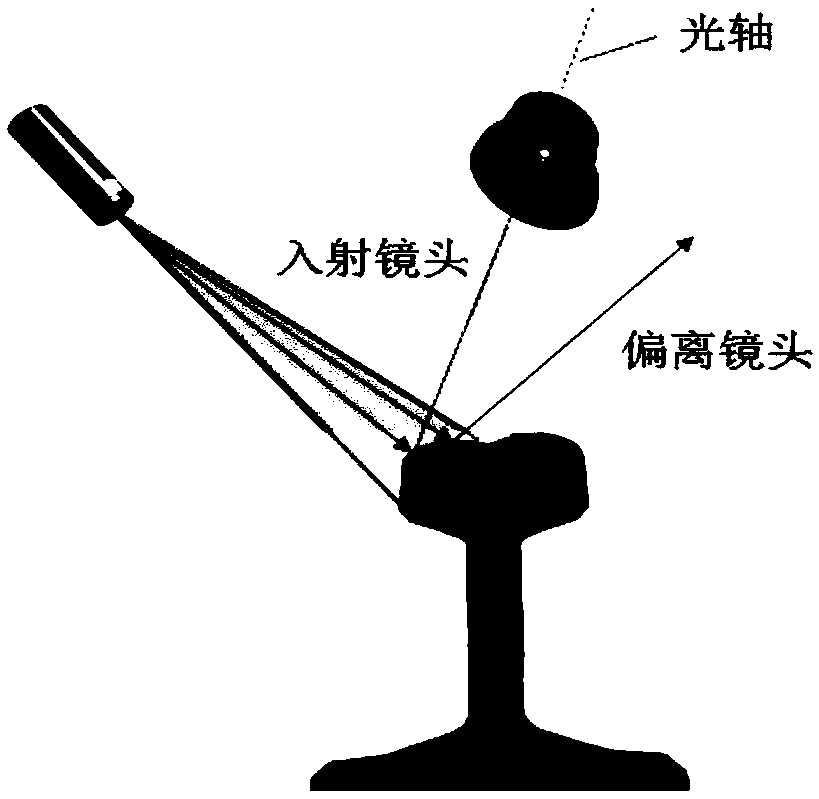
technical field [0001] The invention relates to the technical field of data processing, in particular to a method and device for extracting the laser stripe center of a rail profile in a dynamic driving environment. Background technique [0002] In the line structured light measurement system, the laser beam is projected vertically onto the surface of the object to be measured, and the camera captures the laser stripe image from another angle, and obtains the laser section data according to the triangulation method. Triangulation requires that the contour line projected onto the surface of the object should be infinitely thin, that is, only one pixel wide. However, due to light scattering, the point diffusion effect of the imaging system, etc., the projection image of the actual contour line on the image plane has a certain thickness and is in the shape of a light strip. Therefore, how to quickly and accurately extract the position of the center of the laser stripe and obta...

Claims


Application Information

Patent Timeline
Patent Type & Authority Applications(China)
IPC IPC(8): G06T7/70G06T7/60G06T7/40G06T7/11G06N3/08
CPCG06N3/084G06T7/40G06T7/60G06T7/11G06T7/70
Inventor 王昊王胜春赵鑫欣戴鹏杜馨瑜
Owner RAILWAY INFRASTRUCTURE TESTING RES INST CHINA ACAD OF RAILWAY SCI
Why Eureka
Try Eureka