System for the determination of vessel geometry and flow characteristics

a flow characteristic and geometry technology, applied in image enhancement, angiography, instruments, etc., can solve the problems of not providing complete diagnostic information, patient load of contrast agent and x-ray radiation is however rather high, and the effect of reducing the risk of vascular diseas

Active Publication Date: 2010-06-15
KONINKLIJKE PHILIPS ELECTRONICS NV
View PDF19 Cites 187 Cited by
  • Summary
  • Abstract
  • Description
  • Claims
  • Application Information

AI Technical Summary

Benefits of technology

[0003]Based in this situation it was an object of the present invention to provide means for the determination of vessel geometry and flow characteristics with high accuracy and reduced strain for the patient.
[0005]An investigation system of the aforementioned kind has the advantage that it allows a reconstruction of the three-dimensional vessel geometry and of the flow characteristics based on a single sequence of X-ray projections. The load of the patient with contrast agent and X-radiation is therefore reduced accordingly. Despite the reduced number of available measurements, the reconstruction achieves a high accuracy because it makes use of modeled knowledge on contrast agent dynamics, i.e. the specific increase and decrease of X-ray attenuation—observed as “time-intensity curves” (TICs) in the projection images—due to the flow of contrast agent in the blood stream. Temporal changes associated with the passage of a bolus of contrast agent are thus exploited to obtain information on the vessel geometry and flow characteristics. This often even allows the reconstruction of “difficult” vessel geometries for which conventional methods yield no or ambiguous results.
[0020]In both embodiments described above, an increase in robustness in comparison to algorithms that work on static vessel trees is obtained because the additional information on contrast agent dynamics can solve ambiguities that frustrate the application of conventional methods to acquisitions with a static, completely opaque vessel tree.
[0022]In an alternative embodiment, the data processing unit is adapted to predict a function (c(t, {right arrow over (p)})) that represents the amount of contrast agent at any point in the vascular model when contrast agent is injected upstream and transported by convection and diffusion of a fluid through tubular structures of a known geometry up to this point. This approach yields very realistic TICs as it takes the concrete vessel geometry through which a bolus has flown between injection and observation into account.

Problems solved by technology

Due to the necessary generation of two image sequences, the patient load with contrast agent and X-radiation is however rather high for this method.
Furthermore, as the dynamic flow is observed in one fixed projection geometry, flow information is only available for a subset of vessels which run approximately parallel to the image plane without occlusion from other vessels, therefore not providing complete diagnostic information.

Method used


Image

  • System for the determination of vessel geometry and flow characteristics
  • System for the determination of vessel geometry and flow characteristics
  • System for the determination of vessel geometry and flow characteristics

Examples


Embodiment Construction

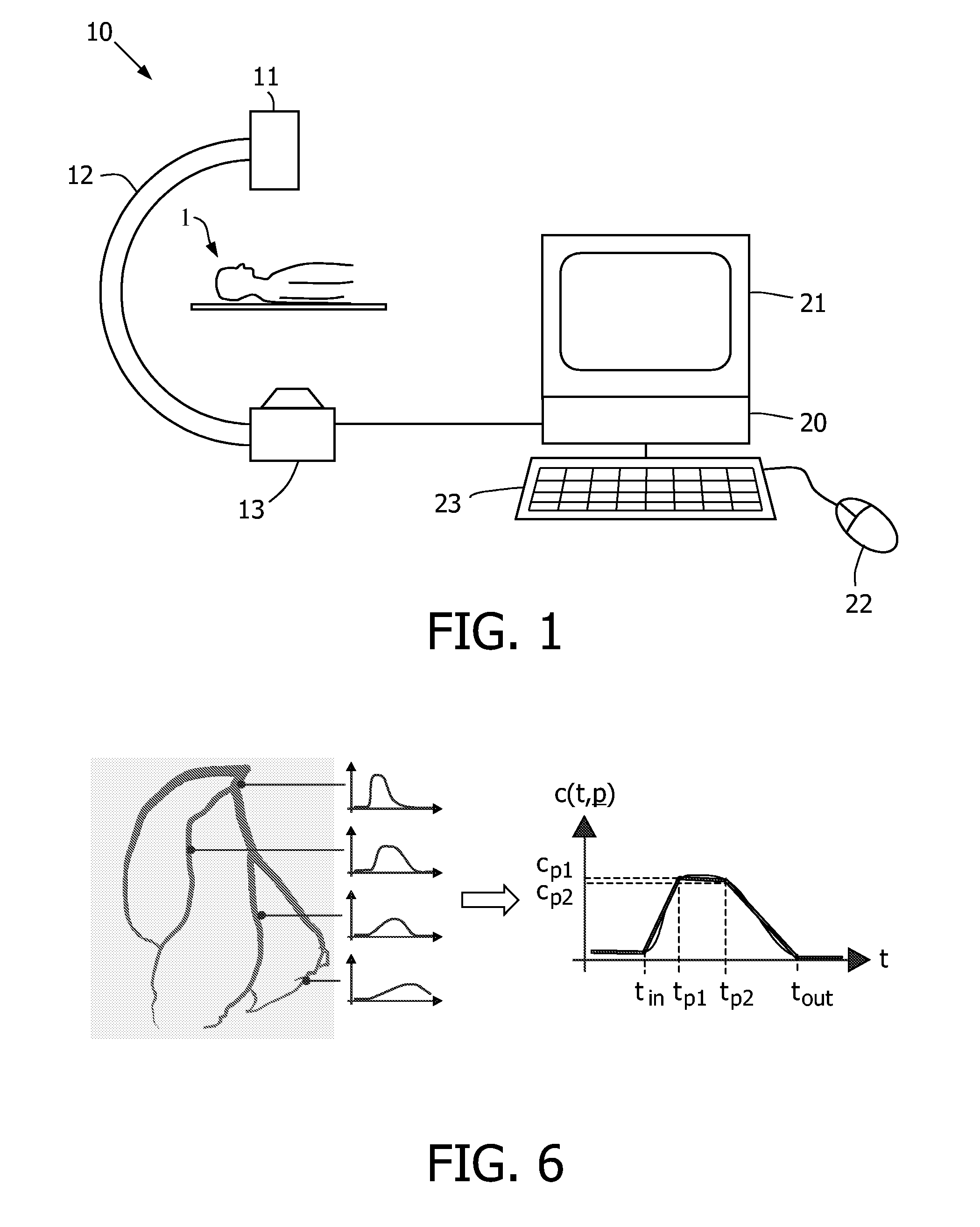
[0039]FIG. 1 shows schematically an investigation system as it may be used in connection with the present invention. The system comprises a rotational X-ray device 10 with an X-ray source 13 facing an X-ray detector 11, wherein both components are coupled via a C-arm 12. A patient 1 is positioned in the centre of the X-ray device 10 such that X-ray projections of the vessel system in a body region of said patient 1 can be generated from different directions. Furthermore, the X-ray device 10 is coupled to a data processing unit 20, for example a workstation, which is adapted to control the X-ray device 10 and particularly to process image data received therefrom. The data processing unit 20 is also connected to a monitor 21 on which a reconstructed vessel tree and its flow characteristics can be displayed, wherein the flow may for example be represented by a film sequence or in a color code of flow velocities. Via a keyboard 23 and a mouse 22 connected to the workstation 20 a user ca...


PUM


Abstract

The invention relates to a method and a system for the simultaneous reconstruction of the three-dimensional vessel geometry and the flow characteristics in a vessel system. According to one realization of the method, vessel segments (41) of a parametric models are fitted to differently oriented X-ray projections (P1, Pk, PN) of the vessel system that are generated during the passage of a bolus of contrast agent, wherein the fitting takes the imaged contrast agent dynamics and physiological a priori knowledge into account. In an alternative embodiment, the vessel geometry is reconstructed progressively along each vessel, wherein a new segment of a vessel is added based on the continuity of the vessel direction, vessel radius and reconstructed contrast agent dynamics.

Description

FIELD OF THE INVENTION[0001]The invention relates to a method and an investigation system for the determination of the vessel geometry and the flow characteristics in the vessel system of a body region.BACKGROUND OF THE INVENTION[0002]For vascular diseases (e.g. neurovascular, peripheral, or coronary), important diagnostic information is gained from the shape of the vascular system in observation and its flow dynamics. Such information can for example assess tumors, ischemic stenoses, and arterio-venous malformations. A system that allows the such diagnostics is known from the US 2003 / 0040669 A1, according to which the vessel geometry is reconstructed in three dimensions based on a first sequence of rotational projections. The flow characteristics are then determined from a second sequence of projections from a constant direction, and matched with the three-dimensional vessel model. Due to the necessary generation of two image sequences, the patient load with contrast agent and X-ra...

Claims


Application Information

Patent Timeline
Patent Type & Authority Patents(United States)
IPC IPC(8): A61B6/02
CPCA61B6/481A61B6/504G06T7/0012G06T11/003G06T2211/404G06T2207/10112G06T2207/10116G06T2207/30104
Inventor WEESE, JUERGENGROTH, ALEXANDRABREDNO, JOERG
Owner KONINKLIJKE PHILIPS ELECTRONICS NV
Why Eureka
Try Eureka