Ink-jet head, method for manufacturing ink-jet head and ink-jet printer having ink-jet head

a technology of inkjet printer and manufacturing method, which is applied in the direction of printing, inking apparatus, etc., can solve the problems of poor printing and so as to achieve effective relaxation of warp, lightening of production yield, and poor printing

Inactive Publication Date: 2005-09-20
BROTHER KOGYO KK
View PDF6 Cites 16 Cited by
  • Summary
  • Abstract
  • Description
  • Claims
  • Application Information

AI Technical Summary

Benefits of technology

[0009]The invention thus provides an ink-jet head capable of relaxing a warp which can cause poor printing and deterioration in a production yield, to provide a method for manufacturing the ink-jet head, and to provide an ink-jet printer having the ink-jet head.
[0012]In this construction, on two surfaces of a main unit in a passage unit, there are respectively fixed a nozzle plate unit and an actuator unit, both of which are made of materials having smaller linear expansion coefficients than that of the main unit. As a result, a warp in the ink-jet head can be relaxed even when the ink-jet head is fixed in the heated state. Moreover, since the warp is relaxed, such problems as poor printing and deterioration in a production yield can be lightened.
[0016]In this construction, on one face of an actuator unit, there is fixed a passage unit made of a material having a linear expansion coefficient larger than that of a material making the actuator unit, in the heated state, whereas on the other face of the actuator unit, there is arranged a support member made of a material having a linear expansion coefficient larger than that of the actuator unit. As a result, a warp in the ink-jet head can be relaxed. Moreover, since the warp is relaxed, such problems as poor printing and deterioration in a production yield can be lightened.
[0020]In this construction, actuator units and fixing portions of a support member on a surface of a passage unit are fixed on the surface of the passage unit and are staggered from each other. Then, a warp, as might otherwise be caused due to the difference in the linear expansion coefficient between the passage unit and the actuator unit, is more effectively relaxed. Since the actuator unit has a smaller linear expansion coefficient than that of the passage unit, a warp convex toward the actuator unit occurs in each of the portions on the surface of the passage unit where the actuator units are fixed. In case the actuator units are fixed in one row on the surface of the passage unit in the longitudinal direction, for example, a warp occurs in an offset state concentratedly along the longitudinal direction where the actuator units are fixed. This kind of offset warp is not sufficiently relaxed even if the support member is fixed on the region of the passage unit where the actuator units are not fixed. On the other hand, when the actuator units are fixed in a staggered shape on the surface of the passage unit and the support member having a larger linear expansion coefficient than that of the actuator units is fixed on the passage unit except the region where the actuator units are fixed so that its fixing portions are arranged in a staggered shape on the surface of the passage unit, the warp is not offset all over the surface of the passage unit. As a result, the warp can be effectively relaxed. Moreover, since the warp is relaxed, such problems as poor printing and deterioration in a production yield can be lightened.

Problems solved by technology

Moreover, since the warp is relaxed, such problems as poor printing and deterioration in a production yield can be lightened.

Method used


Image

  • Ink-jet head, method for manufacturing ink-jet head and ink-jet printer having ink-jet head
  • Ink-jet head, method for manufacturing ink-jet head and ink-jet printer having ink-jet head
  • Ink-jet head, method for manufacturing ink-jet head and ink-jet printer having ink-jet head

Examples


first embodiment

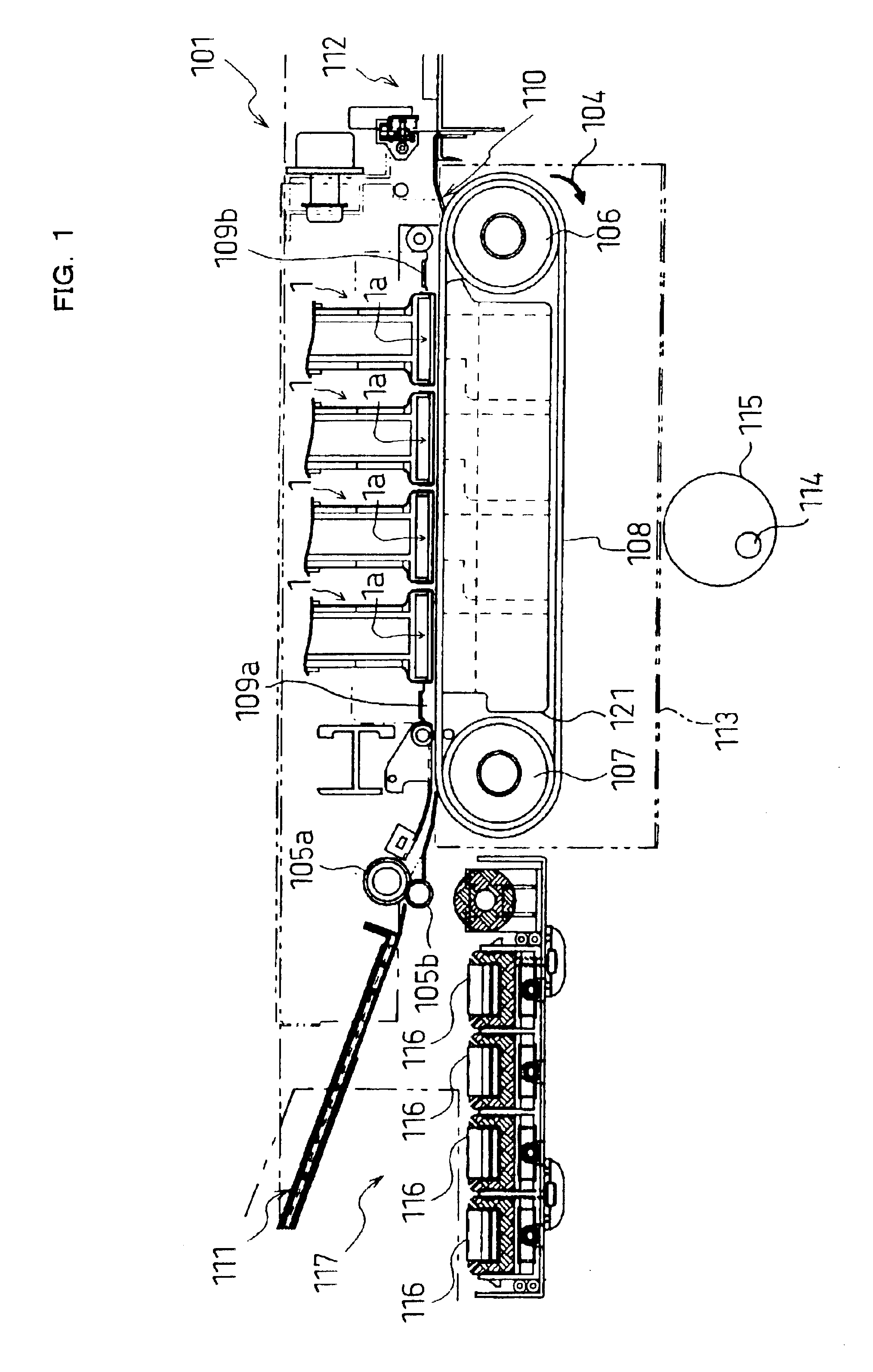
[0042]FIG. 1 is a general view of an ink-jet printer including ink-jet heads according to the invention. The ink-jet printer 101 as illustrated in FIG. 1 is a color ink-jet printer having four ink-jet heads 1. In this printer 101, a paper feed unit 111 and a paper discharge unit 112 are disposed in left and right portions of FIG. 1, respectively.

[0043]In the printer 101, a paper transfer path is provided extending from the paper feed unit 111 to the paper discharge unit 112. A pair of feed rollers 105a and 105b is disposed immediately downstream of the paper feed unit 111 for pinching and putting forward a paper as an image record medium. By the pair of feed rollers 105a and 105b, the paper is transferred from the left to the right in FIG. 1. In the middle of the paper transfer path, two belt rollers 106 and 107 and an endless transfer belt 108 are disposed. The transfer belt 108 is wound on the belt rollers 106 and 107 to extend between them. The outer face, i.e., the transfer face...

second embodiment

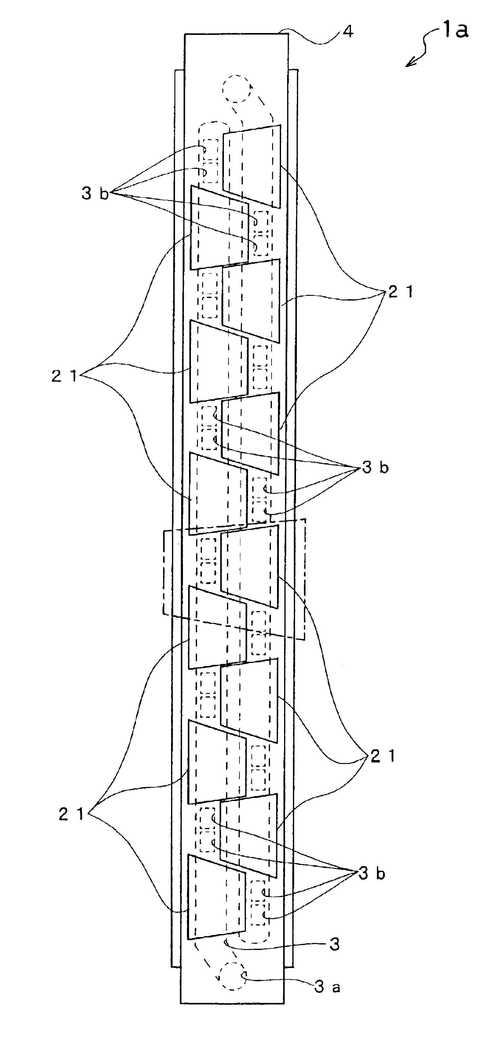
[0129]Moreover, FIGS. 16 and 17 show a modification of the invention. FIG. 16 is an enlarged sectional view corresponding to FIG. 14, and FIG. 17 is a partial plan view corresponding to FIG. 15. In this modification, as shown in FIG. 16, a base block 275 is fixed on the surface of the actuator unit 21. Specifically, the base block 275 is not only fixed to the passage unit 14 at a portion 275c near an opening 203, but also fixed on the upper face of the actuator unit 21 at its lower face 275b. In FIG. 17, roughly hatched regions are bonded regions between the base block 275 and the passage unit 14, and finely hatched regions are bonded regions between the base block 275 and the actuator unit 21 while avoiding the openings 203a, 203b.

[0130]According to this modification, the displacement efficiency of the actuator unit 21 to the pressure chamber 10 can be enhanced, especially in the case of the type, in which a plurality of active layers are laminated and the longitudinal piezoelectr...


PUM


Abstract

An ink-jet head includes a passage unit including a nozzle plate unit having a nozzle plate in which nozzles are formed, and a main unit fixed on the nozzle plate unit in a laminating direction and having a plurality of pressure chambers, each of the plurality of pressure chambers having one end connected with a nozzle and an other end connected with an ink supply source, the plurality of pressure chambers arranged along a plane to neighbor each other, and an actuator unit, fixed on a side of the main unit opposite to a side in which the main unit is fixed on the nozzle plate unit, for changing the volume of each of said pressure chambers.

Description

BACKGROUND OF THE INVENTION[0001]1. Field of Invention[0002]The invention relates to an ink-jet head for printing by ejecting ink onto a record medium, to a method for manufacturing the ink-jet head, and to an ink-jet printer having the ink-jet head.[0003]2. Description of Related Art[0004]In an ink-jet printer, an ink-jet head distributes ink, which is supplied from an ink tank, to pressure chambers. The ink-jet head selectively applies pulse pressure to each pressure chamber to eject ink through a nozzle connected with each pressure chamber. As a means for selectively applying pulse pressure to the pressure chambers, an actuator unit or the like may be used in which ceramic piezoelectric sheets are laminated. The printing operations are carried out while reciprocating such a head at a high speed in the widthwise direction of paper.[0005]In the ink-jet head of the related art, a pressure chamber and an ink passage are formed by subjecting the piezoelectric ceramics to a cutting ope...

Claims


Application Information

Patent Timeline
Patent Type & Authority Patents(United States)
IPC IPC(8): B41J2/14B41J2/16
CPCB41J2/14209B41J2/1609B41J2/1623B41J2/1626B41J2/1642B41J2/1643B41J2002/14225B41J2002/14306B41J2002/14459B41J2002/14491B41J2202/03B41J2202/18B41J2202/20
Inventor SAKAIDA, ATSUOHIROTA, ATSUSHI
Owner BROTHER KOGYO KK
Why Eureka
Try Eureka