Tape Cartridge

Inactive Publication Date: 2011-09-22
SEIKO EPSON CORP
View PDF10 Cites 4 Cited by
  • Summary
  • Abstract
  • Description
  • Claims
  • Application Information

AI Technical Summary

Benefits of technology

[0009]According to this structure, the openable and closable shutter structure is provided on the opening into which the printing head is inserted. This structure prevents entrance of dust into the tape cartridge. Thus, poor printing caused by dust can be avoided.Application Example 2
[0017]According to this structure, the shutter structure moves with the head release mechanism of the tape printer. Thus, the opening is securely opened at the time of printing, and is closed when the tape cartridge is removed from the tape printer without requiring operation by a user. Thus, entrance of dust is prevented even while the tape cartridge is being carried separately. Accordingly, poor printing caused by dust can be avoided.

Problems solved by technology

According to the tape cartridge in the related art described above, there is a possibility that dust enters the inside of the tape cartridge through the opening into which the printing head is inserted.
However, after the package is opened by a user, the opening is constantly exposed to the outside, which allows dust to enter the inside of the tape cartridge.
Thus, problems such as poor printing are caused by the dust adhering to the printing tape or the ink ribbon.

Method used


Image

  • Tape Cartridge
  • Tape Cartridge
  • Tape Cartridge

Examples


Embodiment Construction

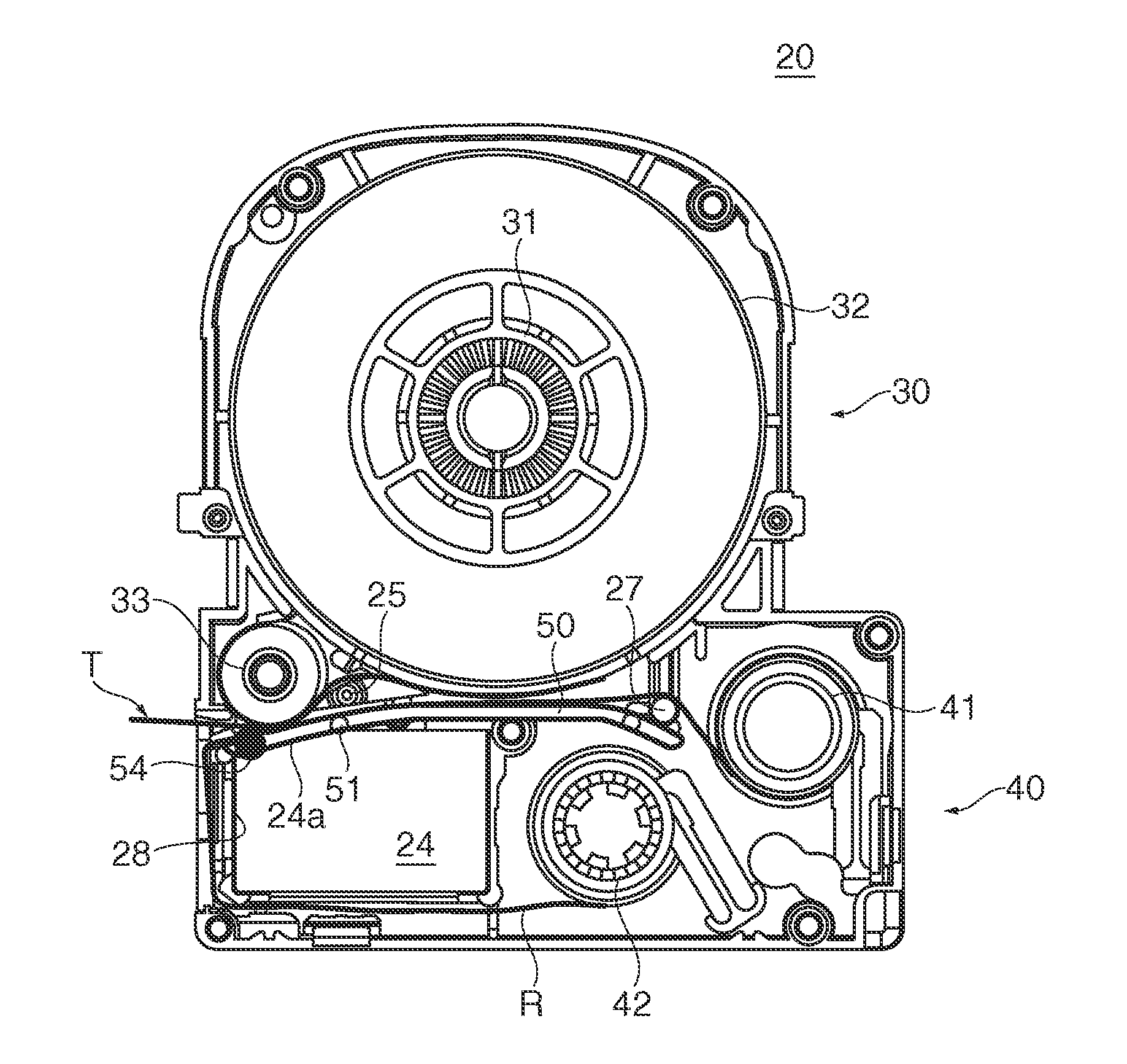
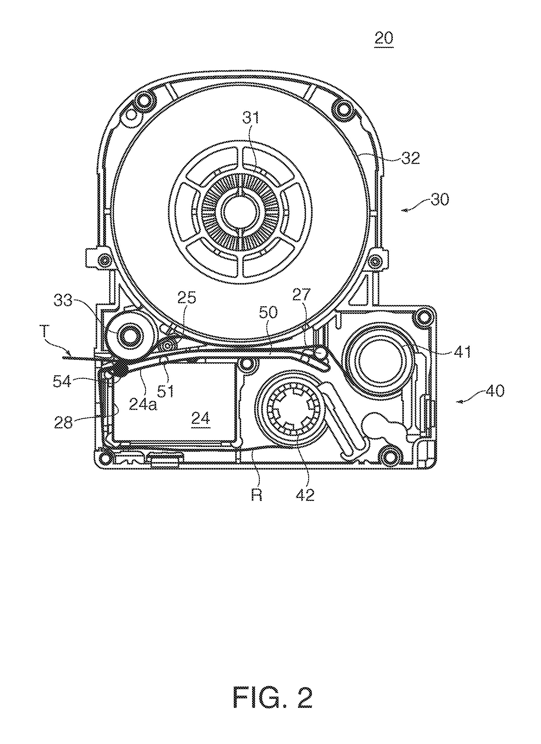
[0026]A tape cartridge and a tape printer according to an embodiment of the invention are hereinafter described with reference to the accompanying drawings. The tape printer performs printing by using a printing unit while drawing a printing tape and an ink ribbon from an attached tape cartridge and delivering the printing tape and the ink ribbon in tension in synchronization with each other, and cuts a printed portion of the printing tape into a label (tape piece).

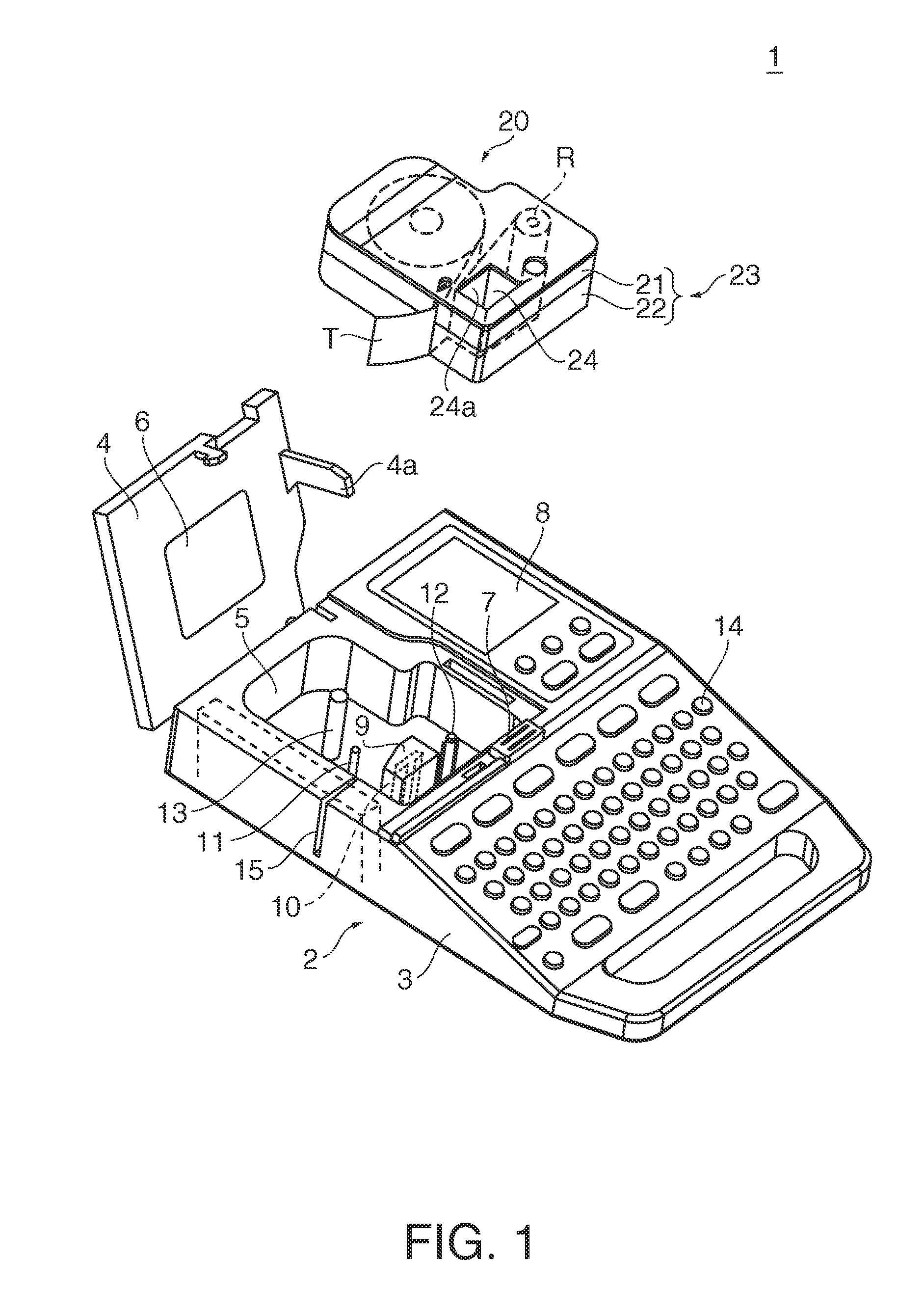
[0027]FIG. 1 is a perspective view illustrating the whole appearance of a tape printer 1 according to an embodiment of the invention. The tape printer 1 includes a device main body 2 which performs a printing process on a printing tape T, and a tape cartridge 20 which stores the printing tape T and an ink ribbon R and is attached to the device main body 2 in such a manner as to be freely attached to and detached from the device main body 2.

[0028]The device main body 2 of the tape printer 1 has a device case 3 constituting...


PUM


Abstract

A tape cartridge attached to an attachment unit of a tape printer includes: a cartridge case which has an upper case and a lower case, wherein the cartridge case includes a tape storing unit storing a printing tape on which printing is performed by using a thermal head provided on the tape printer, a ribbon storing unit storing an ink ribbon used for printing on the printing tape by using the thermal head, and an opening into which the thermal head is inserted, and an openable and closable shutter structure is provided on the opening.

Description

CROSS-REFERENCE TO RELATED APPLICATION[0001]The entire disclosure of Japanese Patent Application No. 2010-062076, filed on Mar. 18, 2010, is expressly incorporated by reference herein.BACKGROUND[0002]1. Technical Field[0003]The present invention relates to a tape cartridge.[0004]2. Related Art[0005]A tape cartridge of a type disclosed in Japanese Utility Model Registration No. 3,041,381, for example, is known. This tape cartridge attached to an attachment unit of a tape printer includes a storage unit for storing a tape core around which a printing tape is wound as a target of printing by a printing head of the printer and a ribbon core around which an ink ribbon is wound, and further includes an opening into which the printing head is inserted.[0006]According to the tape cartridge in the related art described above, there is a possibility that dust enters the inside of the tape cartridge through the opening into which the printing head is inserted. For avoiding this problem, the ta...

Claims


Application Information

Patent Timeline
IPC IPC(8): B41J35/28
CPCB41J15/044B41J35/28
Inventor SHINTANI, AKIHIRO
Owner SEIKO EPSON CORP
Why Eureka
Try Eureka