
Female part, retaining device and pin system for excavators and the like

Active Publication Date: 2019-01-24
METALOGENIA RES & TECH SL
View PDF6 Cites 1 Cited by
  • Summary
  • Abstract
  • Description
  • Claims
  • Application Information

AI Technical Summary

Benefits of technology

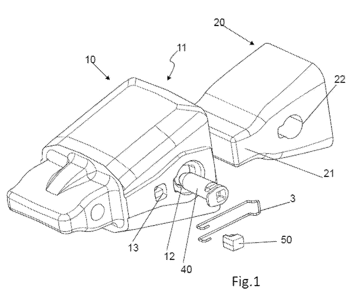
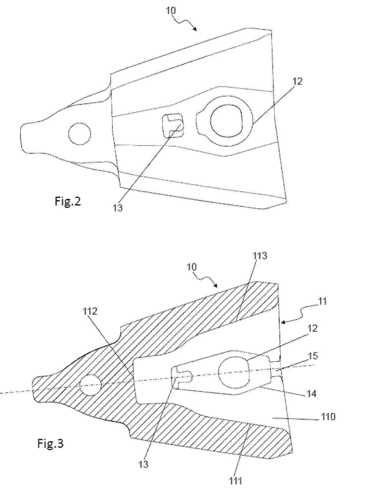
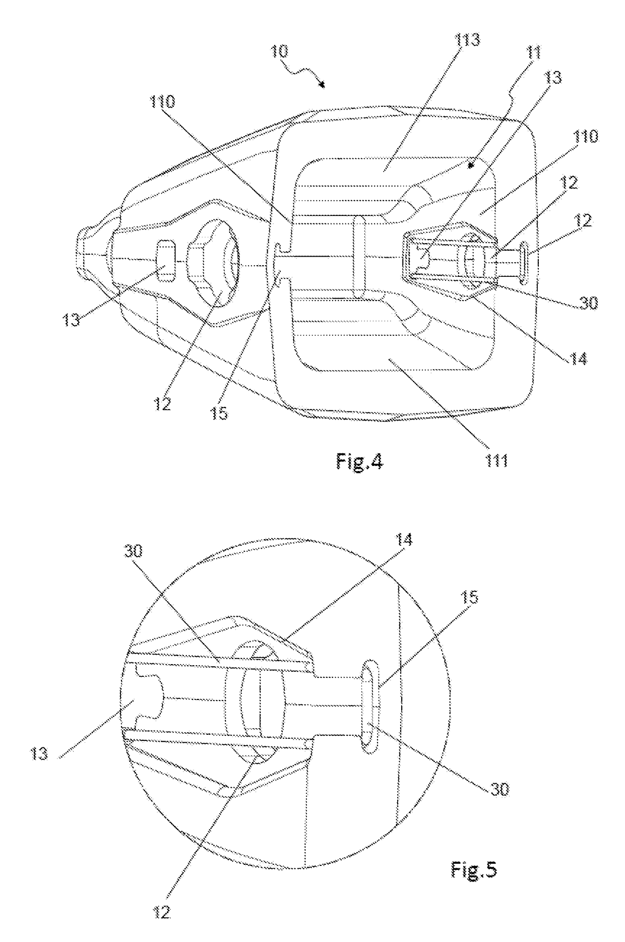
The present invention relates to a female part, a retaining device and a pin system for use in excavators and the like. The female part has a cavity and a male part has a nose that fits into the female part. The female part is detachable from the male part and the position between them is maintained through a pin system. The retaining device keeps the pin in place and prevents it from coming out of its assembly position. The pin system has elastic features and allows for easy replacement without breaking. The invention ensures safe operation and prevents damage to other machines.

Problems solved by technology

However, said wear elements are also exposed to wear impacts and breakages, so they must be replaced, and furthermore, depending on the application, it may be desirable to change the type or the shape of the wear element.
If not, the pin could come out of the coupling and therefore both the pin and the female part may be lost.
The fall of a female part and / or pin could be harmful depending on the work site thereof, possibly causing breakdowns in other machines, such as crushers, working on the same production site as the machine using the teeth, such as mines or quarries for example.
Encapsulating the retaining system in an elastomeric element makes the retaining system useless in tasks where the working temperature is very high since the properties of the elastomer material are lost increasing the possibilities of losing the pin.
Furthermore, the use of an elastomeric element causes interference problems between elements since it has an uncontrolled deformation by pressure.
Another feature of this retaining system is that the use of a clip in combination with an elastomeric material, and the positioning of the assembly in the adaptor element, means that the force needed to be used for assembling and disassembling the pin is high, the use of a hammer, which is unsafe for the user, being necessary and making it incompatible for hammerless systems.
Furthermore, the force needed for assembling and disassembling is high preventing its use in hammerless systems.
Another drawback of this invention is that the retaining device, or washer, does not maintain its position within the cavity by itself and requires the coupling between the tooth and tooth bar.

Method used


Image

  • Female part, retaining device and pin system for excavators and the like
  • Female part, retaining device and pin system for excavators and the like
  • Female part, retaining device and pin system for excavators and the like

Examples


first embodiment

[0065]FIG. 9 shows a perspective view of a retaining device.

[0066]FIGS. 10 and 11 show different views of the retaining device shown in FIG. 9.

[0067]FIG. 12 show a perspective view of a plug.

second embodiment

[0068]FIG. 13 shows a perspective view of a retaining device.

[0069]FIG. 14 shows a detail of the second end of the retaining device.

[0070]FIG. 15 shows a rear perspective view of a female part with the second embodiment of retaining device fixed to it.

[0071]FIG. 16 shows a front perspective view of a female part with the second embodiment of retaining device fixed to it.

[0072]FIG. 17 shows a perspective view of another embodiment of a female part with a second hole that is blind in the inside surface of the wall.

[0073]FIG. 18 shows a lateral section of the female part of FIG. 17.

[0074]FIG. 19 shows a transversal section of the female part of FIGS. 17 and 18 through the second hole.


PUM


Abstract

The present invention relates to a female part, a retaining device and a pin system comprising said device, said female part and a male part, to assure the retention between the female part and a male part used in excavators and the like. The female part has a cavity and can be a wearing element, a tooth or an intermediate part (part between a point and a weld on or cast nose in a three part system) and the male part has a nose to be introduced into the cavity of the female part and this will usually be a tooth-holder, intermediate, cast nose, weld-on nose or an adapter.

Description

OBJECT OF THE INVENTION[0001]The present invention relates to a female part, a retaining device and a pin system comprising said device, said female part and a male part, to assure the retention between the female part and a male part used in excavators and the like. The female part has a cavity and can be a wearing element, a tooth or an intermediate part (part between a point and a welded on or cast nose in a three part system) and the male part has a nose to be introduced in the cavity of the female part and this will usually be a tooth-holder, intermediate, cast nose, weld-on nose or an adapter.[0002]The female part is coupled to the male part, maintaining these two parts coupled through a pin system comprising the retention device. The female part is coupled in a detachable manner to the male part and the position between both is maintained due to a pin that interacts with a retaining device that also keeps the pin in its position. Said pin system prevents the female part from ...

Claims


Application Information

Patent Timeline
IPC IPC(8): E02F9/28
CPCE02F9/2841E02F9/2858
Inventor ORTIZ GARCIA, JUSTO JESUSTUTO, JOANPEREZ SORIA, FRANCISCOTRIGINER BOIXEDA, JORGEGIMENO TORDERA, ALBERT
Owner METALOGENIA RES & TECH SL
Learn More