Gas/liquid contacting apparatus

a technology of gas/liquid contact and apparatus, which is applied in the direction of combustion-air/fuel-air treatment, carburettant air, and separation processes, etc., and can solve the problems of other detrimental effects on the gas/liquid conta

Inactive Publication Date: 2005-09-27
AMT INT INC
View PDF13 Cites 21 Cited by
  • Summary
  • Abstract
  • Description
  • Claims
  • Application Information

AI Technical Summary

Problems solved by technology

There is a problem with a gas / liquid contacting apparatus in that liquid droplets and / or solids entrained in gas fed to the apparatus, particularly when the gas is at a high velocity, can prevent effective passage of gas upwardly through, for example, tray perforations and packings, and have other detrimental effects on the gas / liquid contact, see, for example, column 1, line 66, to column 2, line 12, of U.S. Pat. No. 5,895,608, referred to above.
However, no steam / entrained liquid droplets separation takes place in the vapor feed line, with entrained substance depleted steam exiting the feed line by a different outlet than the separated droplets, and so a significant amount of liquid droplets remains entrained in the steam which passes upwardly from the feed line.

Method used


Image

  • Gas/liquid contacting apparatus
  • Gas/liquid contacting apparatus
  • Gas/liquid contacting apparatus

Examples


Embodiment Construction

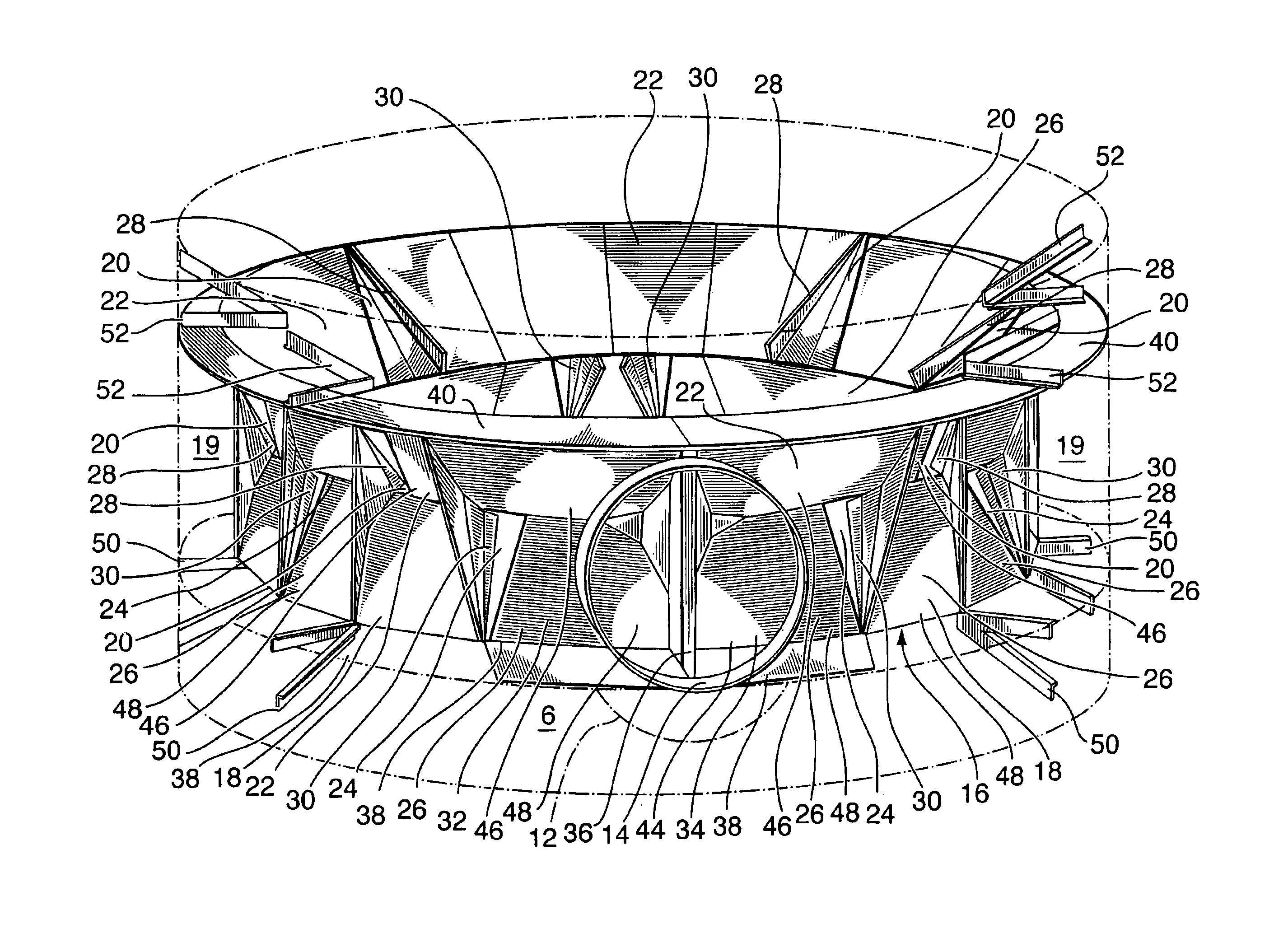
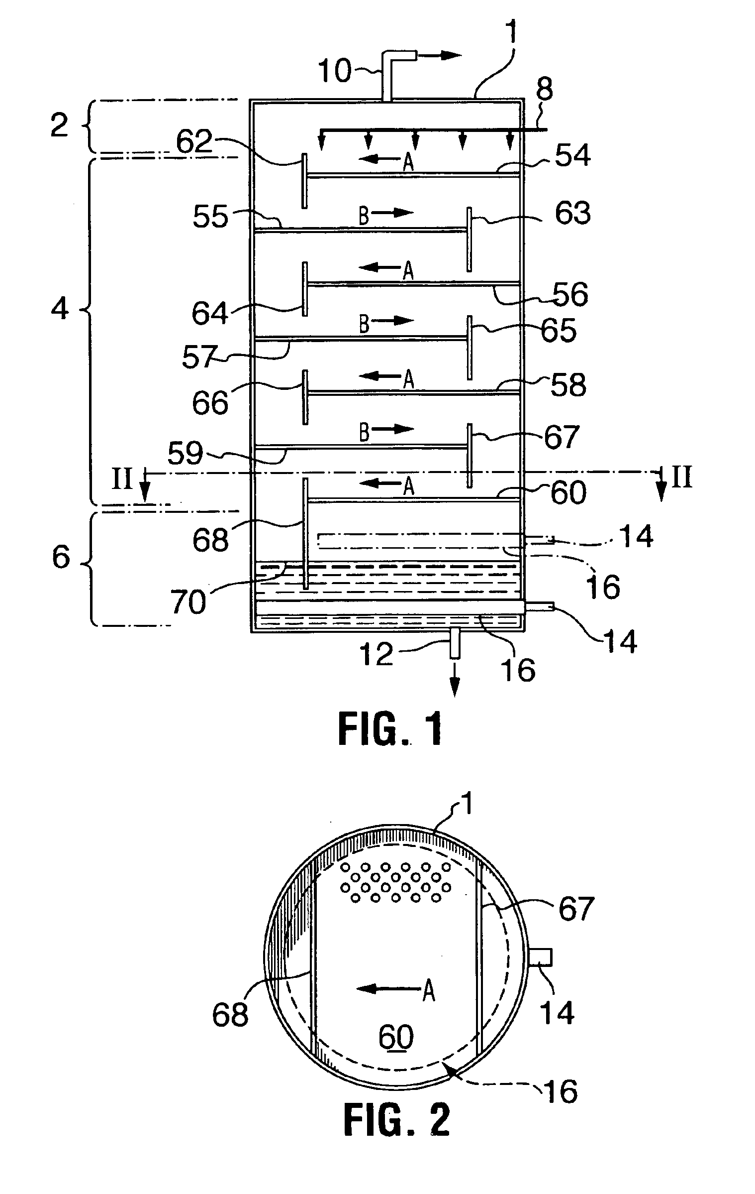
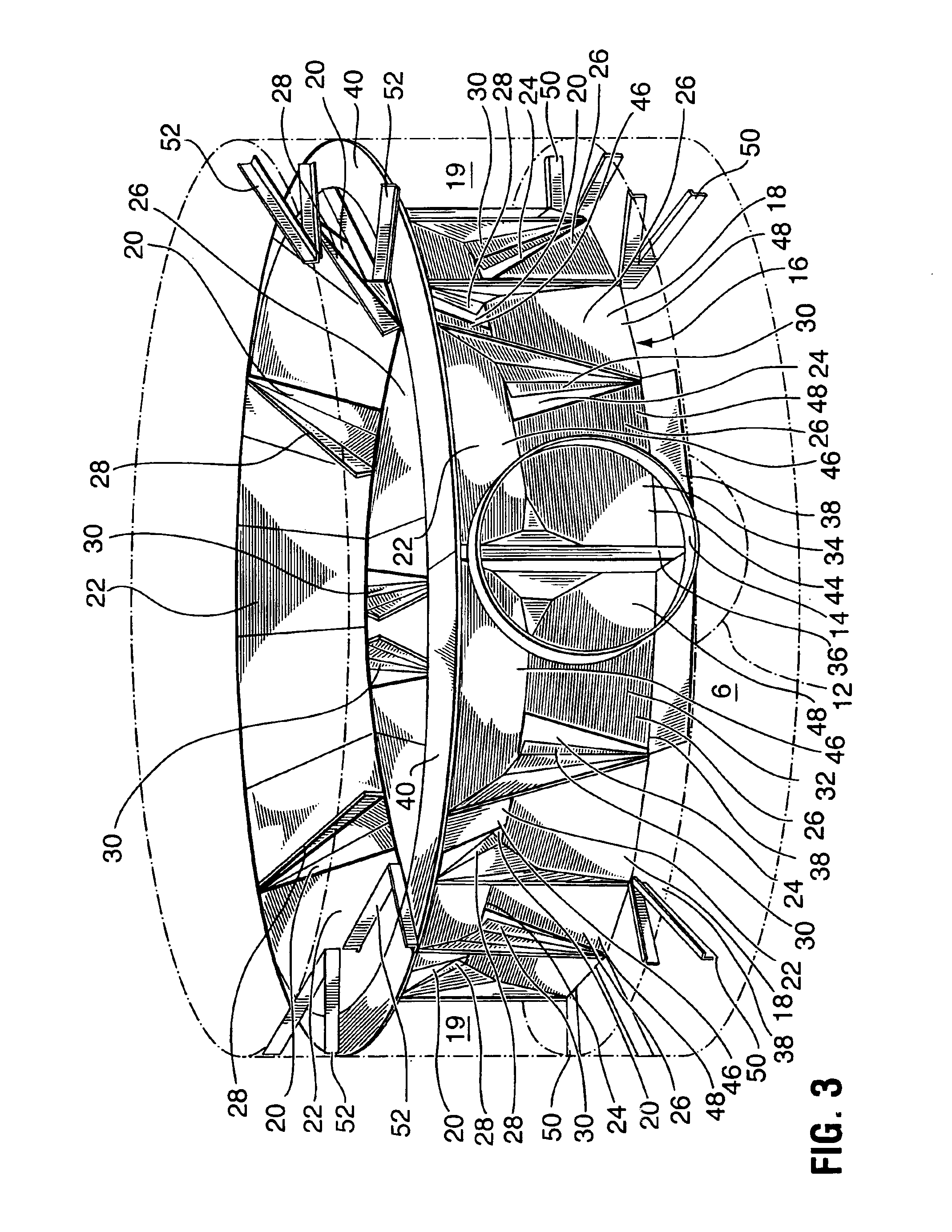
[0034]In FIG. 1 to 3, there is shown a gas / liquid contacting apparatus, which may be, for example, a hydrocarbon fractionating apparatus, comprising,[0035]a) an upwardly extending column 1 having an interior comprising, an upper section 2, a gas / liquid permeable, gas / liquid contacting, intermediate section 4, and a lower, liquid collecting section 6,[0036]b) liquid inlet means 8 to, and gas outlet means 10 from, the upper section 2,[0037]c) liquid outlet means 12 from, and gas inlet means 14 to, the lower section 6, and[0038]d) an entrained substance depleting, gas distributing assembly, generally designated 16, in the lower section 6, the assembly 16 comprising,[0039]i) a gas conveying duct 18 (FIG. 3) connected to the gas inlet 14, and having an interior 19 that decreases in cross sectional area downstream from the gas inlet 14, the duct 18 extending around at least a major portion of the lower section 6, and having entrained substance depleted gas outlets 20, at spaced positions ...


PUM

PropertyMeasurementUnit
surface contact areaaaaaaaaaaa
velocityaaaaaaaaaa
permeableaaaaaaaaaa

Abstract

The lower, liquid collecting section of a gas / liquid contacting column has an entrained substance depleting duct extending therearound wherein gas, for example, steam is fed by the duct into the lower section, steam depleted by gravity of liquid droplets, is deflected upwardly by deflectors in the duct through duct openings into a central, upper region of the lower section, while steam with the droplets is deflected downwardly by deflectors in the duct through other duct openings towards a liquid pool in the lower section. Any other liquid and / or solids entrained in the gas (steam) are also deflected downwardly in this manner.

Description

FIELD OF THE INVENTION[0001]This invention to a gas / liquid contacting apparatus.BACKGROUND OF THE INVENTION[0002]There are various types of gas / liquid contacting apparatus wherein liquid passing downwardly through casing is contacted therein by gas passing upwardly through perforated trays which partition the casing at different levels.[0003]In one type of gas / liquid contacting apparatus the liquid flows across the trays and is frothed thereon by gas permeating the tray perforations, see, for example, U.S. Pat. Nos. 2,005,316, dated Jun. 18, 1935, F. N. Hall, U.S. Pat. No. 3,022,054, dated Feb. 20, 1962, M. H. Kotzebue, and U.S. Pat. No. 5,895,608, dated Apr. 20,1999, A. T. Lee, K. Wu and L. Burton.[0004]In another type of gas / liquid contacting apparatus ordered or randomly distributed packing elements of packed beds are supported by the trays. These beds increase the surface contact area between gas and liquid in the apparatus. The packed beds may be catalyst packed beds, see, for ...

Claims


Application Information

Patent Timeline
Patent Type & Authority Patents(United States)
IPC IPC(8): B01D3/00B01D3/34B01D3/38B01D3/14B01D3/32
CPCB01D3/008B01D3/32B01D3/38
Inventor LEE, ADAM T.BURTON, LARRY W.LEMON, FRANCIS W.
Owner AMT INT INC
Why Eureka
Try Eureka