Method and apparatus for improving vision and the resolution of retinal images
Inactive Publication Date: 2005-09-27
UNIVERSITY OF ROCHESTER
View PDF66 Cites 116 Cited by
Summary
Abstract
Description
Claims
Application Information
AI Technical Summary
This helps you quickly interpret patents by identifying the three key elements:
Problems solved by technology
Method used
Benefits of technology
[0008]In view of the foregoing, it is apparent that there exists a need in the art for a method of and an apparatus for producing ophthalmic optical elements that provide improved or supernormal vision over that which is currently available, as well as high resolution retinal
Problems solved by technology
Despite significant advances in spectacle and contact lens design, current ophthalmic lenses still can only correct defocus and astigmatism.
These high order aberrations of the eye not only blur images formed on the retina, which impairs vision, but also blur images taken of the living human retina.
There have been two obstacles that prevent the use of specially-designed optical elements to correct aberrations beyond defocus and astigmatism in the eye.
First, quantitative measurement of the irregular aberrations of the eye has not been possible.
Second, a mechanism to correct the monochromatic aberrations of the eye other than defocus and astigmatism has not been demonstrated.
They cannot measure the complete wave aberration of the eye, which includes all aberrations left unc
Method used
Image
Click on the blue label to locate the original text in one second.
Reading with bidirectional positioning of images and text.
Examples
Embodiment Construction
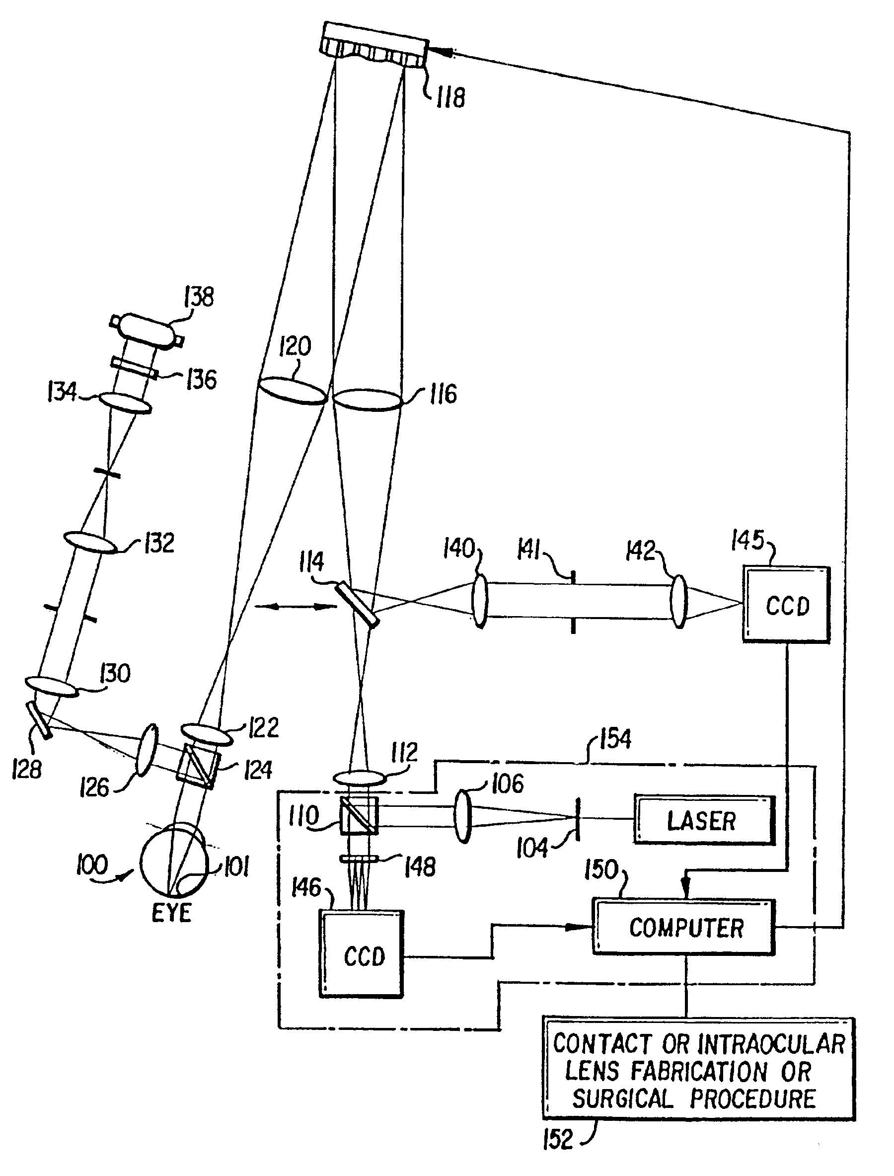
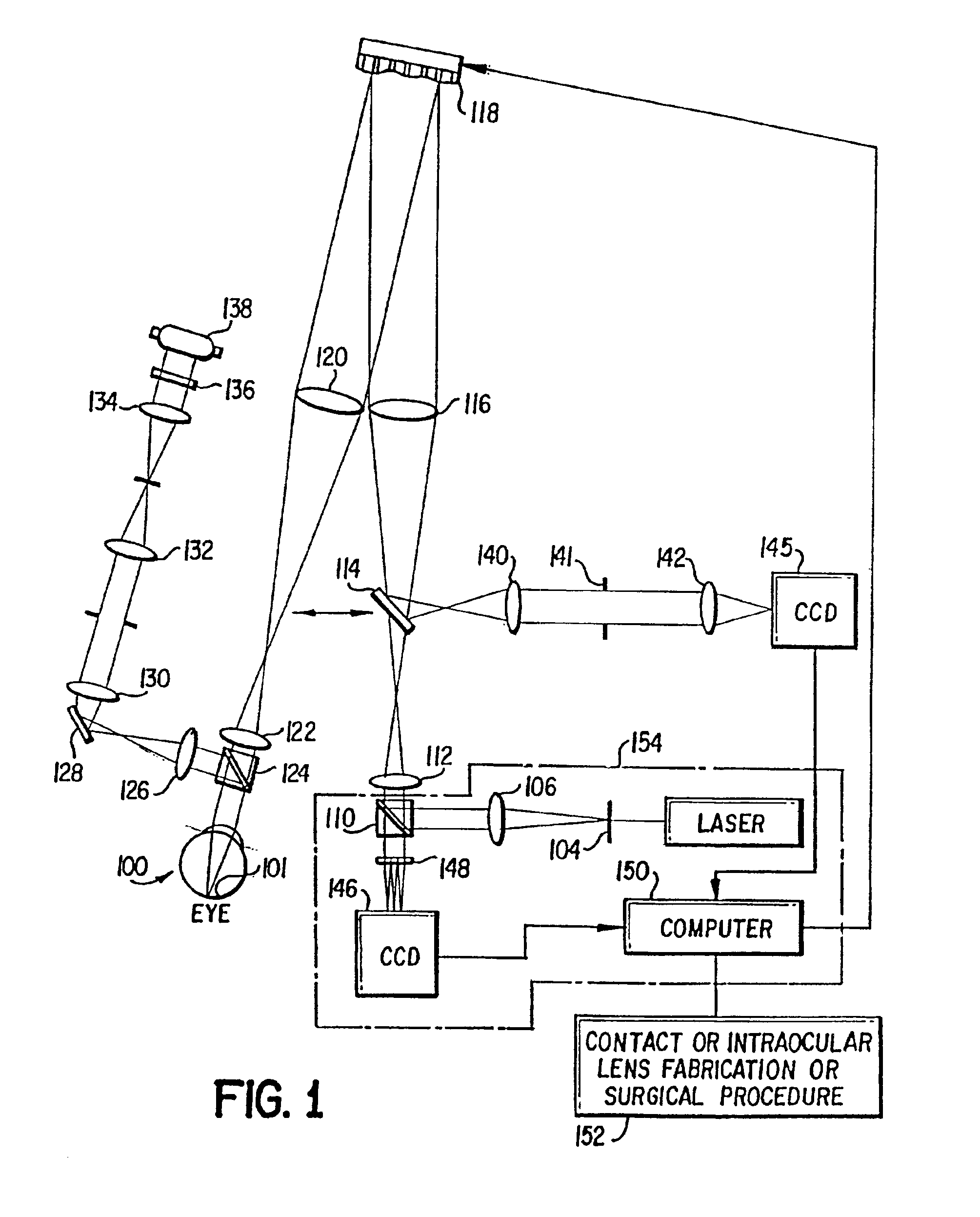
[0023]Referring now to FIG. 1, there is shown, in schematic diagram form, the apparatus of the present invention which can be used to both improve visual performance and to provide high resolution retinal images of eyes. The apparatus of the present invention, as shown in FIG. 1, measures the aberrations of the eye using a Hartmann-Shack wavefront sensor and then corrects them in a closed feedback loop with a compensating optical component such as a deformable mirror.
[0024]To measure the eye's wave aberration, a point source is produced on the retina by a laser 102. The light from the laser 102, is controlled by a shutter (not shown). The laser light passes through a spatial filter 104 and is collimated by an achromatic doublet lens 106. The collimated laser beam is reflected by the polarizing beamsplitter 110, passes through the lenses 112 and 116, and is incident onto a deformable mirror 118. The laser beam reflected from the deformable mirror 118 is focused by the lens 120, passe...
PUM
Abstract
A method of and apparatus for improving vision and the resolution of retinal images is described in which a point source produced on the retina of a living eye by a laser beam is reflected from the retina and received at a lenslet array of a Hartmann-Shack wavefront sensor such that each of the lenslets in the lenslet array forms an aerial image of the retinal point source on a CCD camera located adjacent to the lenslet array. The output signal from the CCD camera is acquired by a computer which processes the signal and produces a correction signal which may be used to control a compensating optical or wavefront compensation device such as a deformable mirror. It may also be used to fabricate a contact lens or intraocular lens, or to guide a surgical procedure to correct the aberrations of the eye. Any of these methods could correct aberrations beyond defocus and astigmatism, allowing improved vision and improved imaging of the inside of the eye.
Description
REFERENCE TO RELATED APPLICATION[0001]The present application is a continuation of U.S. patent application No. Ser. 09 / 628,690, filed Jul. 28, 2000 now U.S. Pat. No. 6,379,005, which is a continuation of U.S. patent application Ser. No. 09 / 346,309, filed Jul. 2, 1999, now U.S. Pat. No. 6,095,651, which is a continuation of U.S. patent application Ser. No. 09 / 071,794, filed May 4, 1998, now U.S. Pat. No. 5,949,521, which is a continuation of U.S. patent application Ser. No. 08 / 772,977, filed Dec. 23, 1996, now U.S. Pat. No. 5,777,719.BACKGROUND OF THE INVENTION[0002]The present invention is directed to a method of and an apparatus for improving vision and the resolution of retinal images. More particularly, the present invention is directed to a method of and an apparatus for measuring and correcting the wave aberration of the eye such that the measured data can be used to develop corrective optical elements for improving the optical quality of the eye.[0003]Despite significant advan...
Claims
Application Information
Patent Timeline
Application Date:The date an application was filed.
Publication Date:The date a patent or application was officially published.
First Publication Date:The earliest publication date of a patent with the same application number.
Issue Date:Publication date of the patent grant document.
PCT Entry Date:The Entry date of PCT National Phase.
Estimated Expiry Date:The statutory expiry date of a patent right according to the Patent Law, and it is the longest term of protection that the patent right can achieve without the termination of the patent right due to other reasons(Term extension factor has been taken into account ).
Invalid Date:Actual expiry date is based on effective date or publication date of legal transaction data of invalid patent.