Highly efficient luminaire having optical transformer providing precalculated angular intensity distribution and method therefore

a transformer and high-efficiency technology, applied in the field of lighting systems, can solve the problems of excessive power consumption, insufficient light redirection in lighting systems, and lamps not providing adequate light to drivers located far away

Inactive Publication Date: 2005-10-04
FARLIGHT
View PDF8 Cites 41 Cited by
  • Summary
  • Abstract
  • Description
  • Claims
  • Application Information

AI Technical Summary

Benefits of technology

[0011]In another embodiment, the present invention provides an apparatus for transforming and emitting light that can include a light source that emits light, a light transformer having a curved circular reflective interior surface, the reflective interior surface reflecting the light emitted by the light source in a predetermined pattern with a substantial amount of light being reflected close to an axis coincident with a radial line defining a radius of the circular reflective interior surface and an optical window the transmits the light to the exterior of the light transformer. The reflective interior surface can reflect the light at an angle α to achieve an intensity proportional to 1 / (tan2 α). The reflective interior surface can further reflects light rays of the light at different angles to compensate for an inverse proportional relationship between perceived intensity and distance from a light source.

Problems solved by technology

Unfortunately, these lamps require excessive amounts of power.
These lighting systems do not sufficiently redirect light in an optimal pattern for drivers.
For example, the lamps do not provide adequate light to drivers located far away from the lamps.
Accordingly, the lamps also do not compensate for an inverse square relationship of illuminance to distance as a driver approaches the lamp.
In particular, the lamps do not adjust for the fact that a driver can see the lamp better when the driver is closer to the lamp.
Accordingly, they have low efficiency.

Method used


Image

  • Highly efficient luminaire having optical transformer providing precalculated angular intensity distribution and method therefore
  • Highly efficient luminaire having optical transformer providing precalculated angular intensity distribution and method therefore
  • Highly efficient luminaire having optical transformer providing precalculated angular intensity distribution and method therefore

Examples


Embodiment Construction

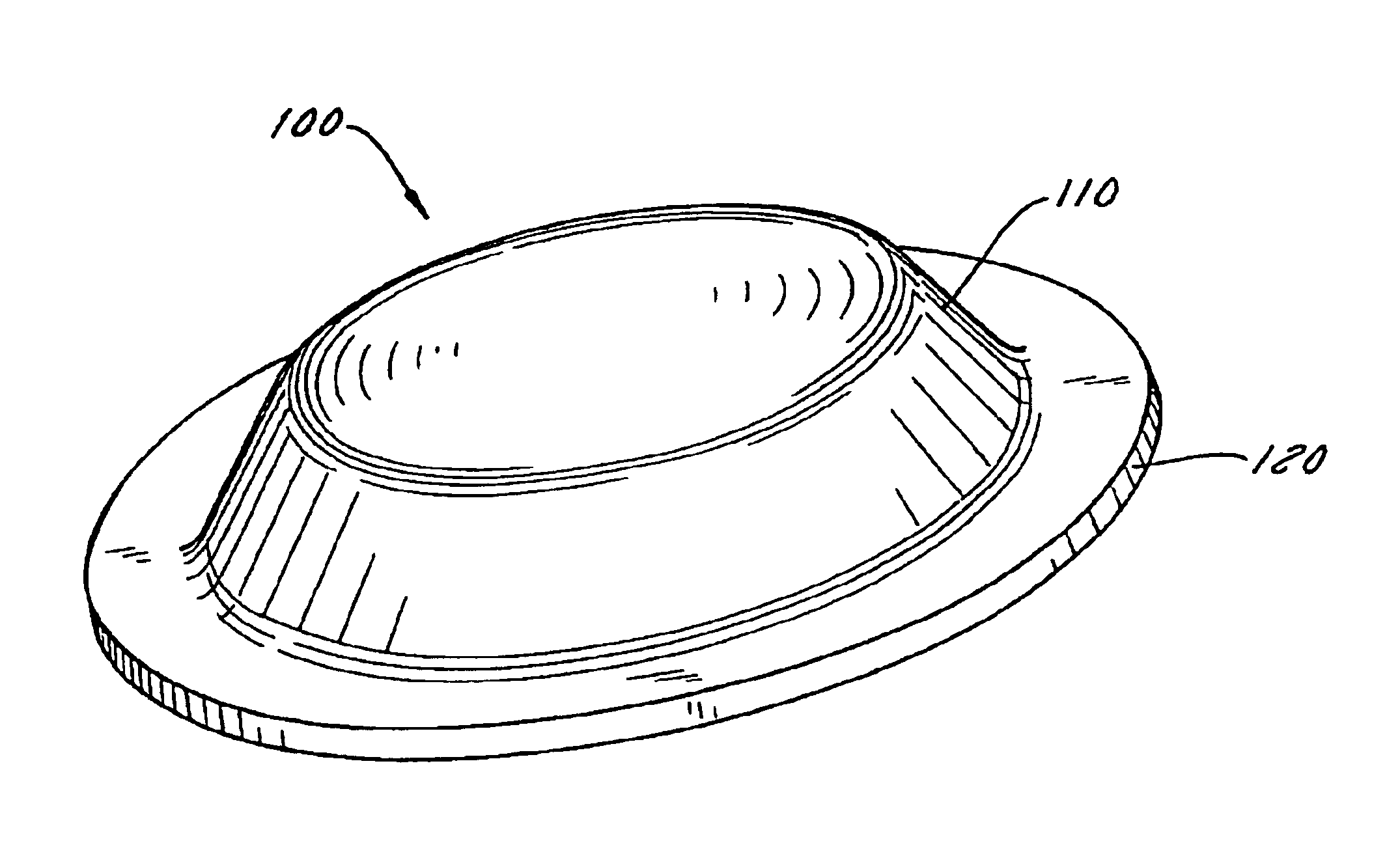
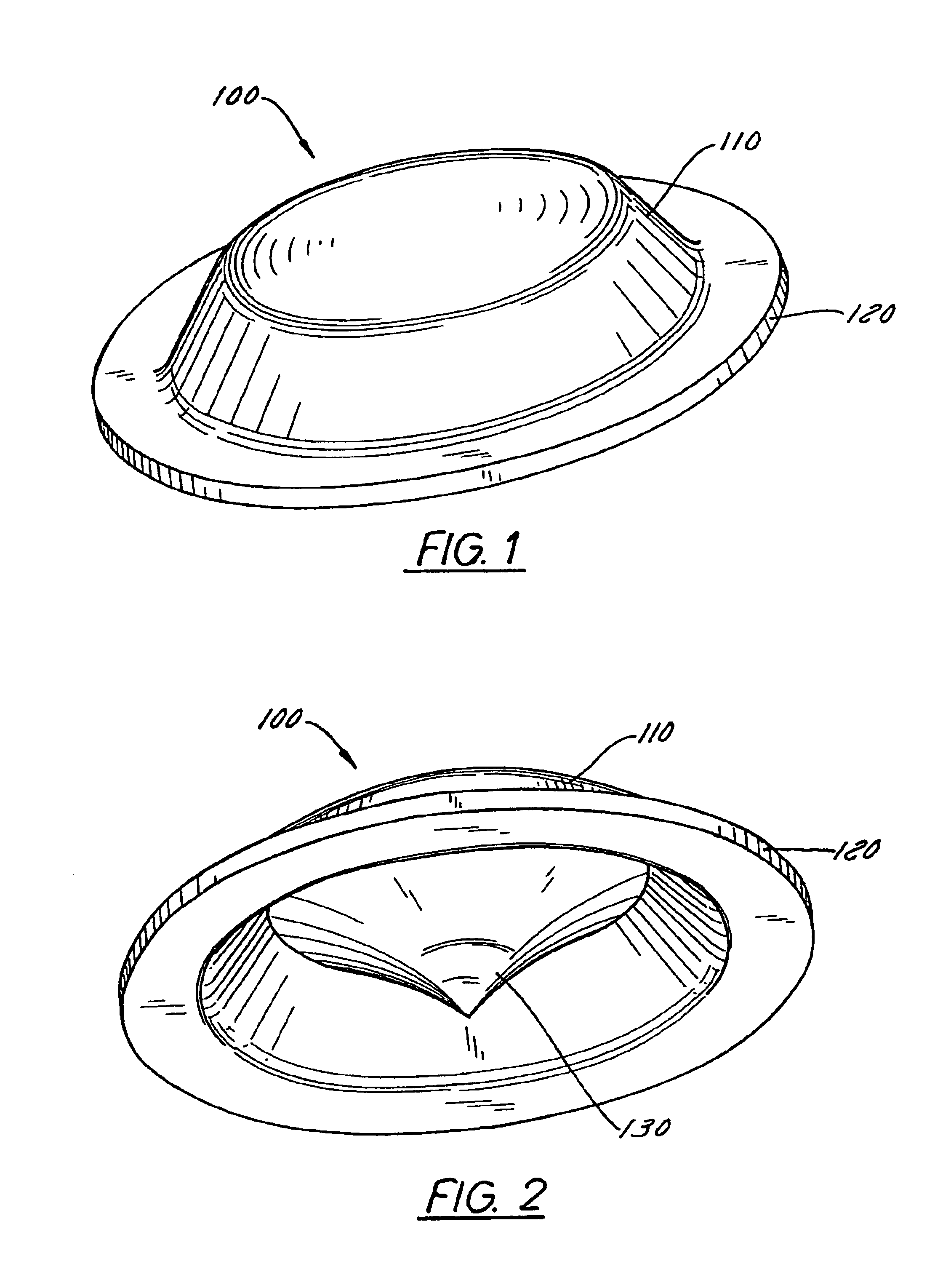
[0030]FIG. 1 is an exemplary perspective view of an integrated omnidirectional light transformer 100 according to one embodiment. The integrated light transformer 100 can include an optical window 110 and a support 120. The optical window 110 may comprise an omnidirectional window or it may comprise any other means for transmitting light, such as lenses, diffusers or open areas. In operation, when it is desirable to distribute light out of the light transformer 100 in a 360 degree pattern, the light transformer 100 can be circular as illustrated. Other shapes and various masks can be used to effectuate different light distribution patterns. For example, part of the optical window 110 may be masked in order to distribute light out of only a portion of the light transformer 100.

[0031]FIG. 2 is another exemplary perspective view of the light transformer 100 according to one embodiment. FIG. 2 illustrates that the light transformer 100 can further include an arbitrary aspherical reflect...


PUM


Abstract

A highly efficient luminaire. The luminaire includes a light source that emits light. The emitted light is redirected by a light transformer having a curved circular reflective interior surface, the reflective interior surface reflecting the light in a predetermined pattern. A substantial amount of light being may be reflected close to an axis coincident with a radial line defining a radius of the circular reflective interior surface. Additionally, a substantial amount of light may be reflected in a pattern with low divergency or parallel with an axis of the light transformer. The light is transmitted to the exterior of the luminaire by an optical window.

Description

[0001]This application is a continuation application based on U.S. Ser. No. 09 / 566,521 filed on May 8, 2000, now U.S. Pat. No. 6,543,911 issued Apr. 8, 2003.BACKGROUND OF THE INVENTION[0002]1. Field of Invention[0003]The present invention is directed generally to lighting systems. More particularly, the present invention is directed to light transforming devices that provide a precisely determined light distribution pattern, such as those used for navigation, obstructions and other signal lights.[0004]2. Description of Related Art[0005]Presently, lighting systems are used to mark obstructions and curves on roadways and paths on airport taxiways and runways. For example, airports incorporate a system of lighting to provide guidance to approaching and taxiing aircraft. Thousands of halogen lamps can be used in airports. Unfortunately, these lamps require excessive amounts of power.[0006]In roadway lighting systems, lamps are placed around the obstructions and along roadway curves to s...

Claims


Application Information

Patent Timeline
Patent Type & Authority Patents(United States)
IPC IPC(8): E01F9/04E01F9/06F21V7/04F21K7/00F21V7/00F21S8/00B64F1/20F21V5/04F21K99/00F21S2/00F21V7/06F21W111/06F21Y101/02G08B5/00
CPCB64F1/20E01F9/065F21V5/046F21V7/0008F21V7/0091F21V7/04F21V21/0824F21V13/04B64C2027/8236F21S10/06F21W2111/06F21Y2101/02Y10S362/80B64F1/205E01F9/559F21Y2103/33F21Y2115/10B64D2203/00
Inventor RIZKIN, ALEXANDERTUDHOPE, ROBERT H.AGUROK, IL'YARUIZ, DAVID
Owner FARLIGHT
Why Eureka
Try Eureka