Locking arrangement for a movable hardtop vehicle roof

a technology for hardtop vehicles and locking hooks, which is applied in the direction of roofs, superstructure subunits, mechanical devices, etc., can solve the problems of requiring a correspondingly extensive operating linkage, and achieve the effect of substantially reducing the cost of the force transmission mechanism between the drive structure and the locking hooks

Inactive Publication Date: 2005-10-11
CTS FAHRZEUG DACHSYST
View PDF11 Cites 10 Cited by
  • Summary
  • Abstract
  • Description
  • Claims
  • Application Information

AI Technical Summary

Benefits of technology

[0009]This arrangement provides for a symmetric force distribution over the width of the vehicle roof. Furthermore, the arrangement is relatively small because the two locking hooks are arranged side-by-side in the center area of the vehicle. The two locking hooks are part of a common locking mechanism, which includes a support receiving both locking hooks and, in a particularly expedient embodiment, also a common operating member, which actuates both locking hooks at the same time. The integration into a common support part gives the optical appearance of a single compact locking member. Still, with the double hook arrangement a symmetric evenly distributed force transmission to the vehicle roof is achieved. Widely spaced locking hooks with long, transversely extending operating levers are not necessary whereby the expenditures for the force transmission mechanism between the drive structure and the locking hooks is substantially reduced.
[0010]Another advantage resides in the fact that, because of the central location of the locking arrangement, additional tasks can be performed by the locking arrangement. It is, for example, possible to interlock the front roof part and the immediately adjacent rear roof part. The interlocking with the adjacent rear roof part is achieved kinematically together with the locking of the front roof part to a vehicle body component, particularly the windshield frame and is achieved by way of a common single drive.

Problems solved by technology

The two locking hooks however are widely spaced from each other in the transverse direction, which requires a correspondingly extensive operating linkage.

Method used


Image

  • Locking arrangement for a movable hardtop vehicle roof
  • Locking arrangement for a movable hardtop vehicle roof
  • Locking arrangement for a movable hardtop vehicle roof

Examples


Embodiment Construction

[0018]In the figures, identical components are designated by the same reference numerals.

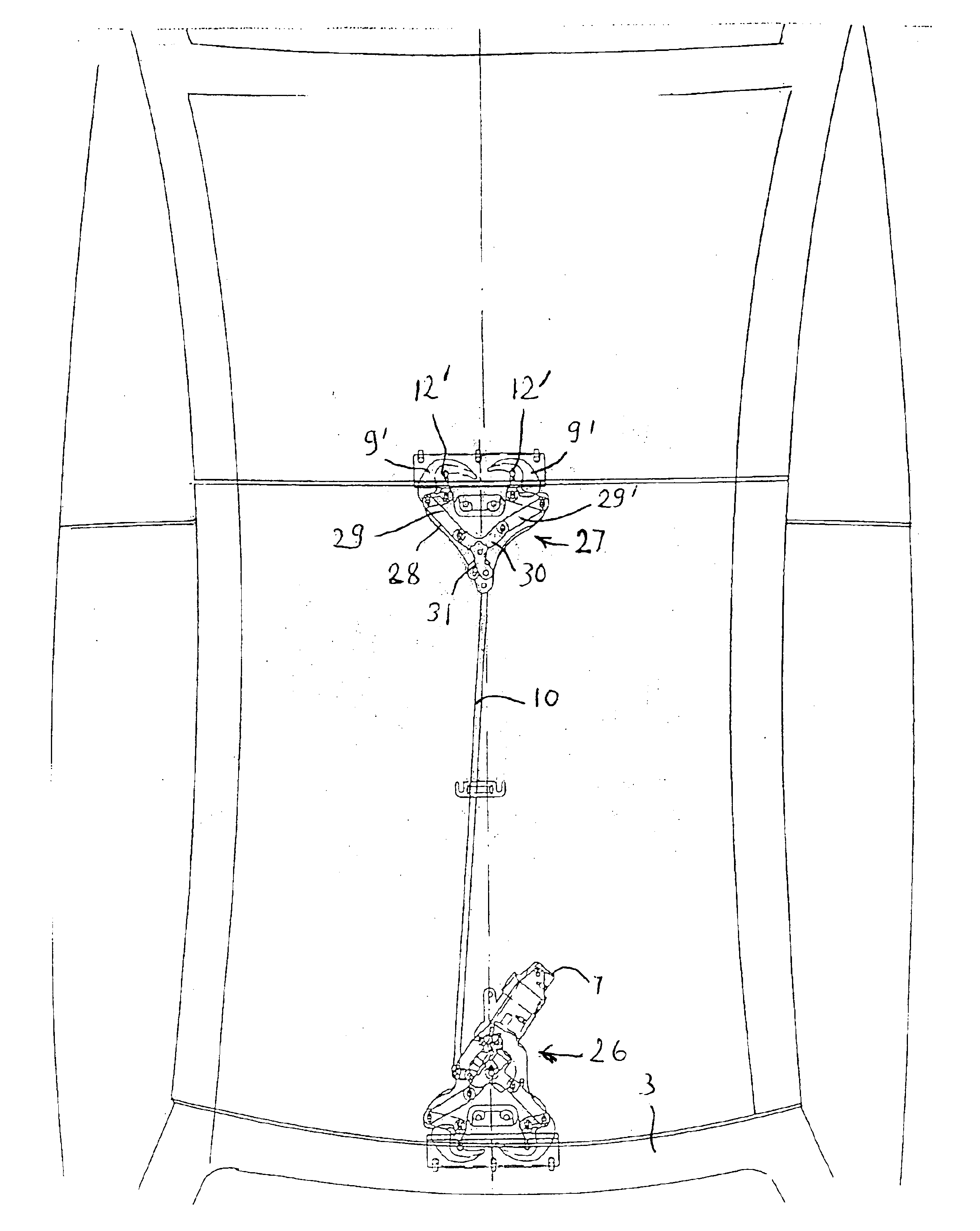
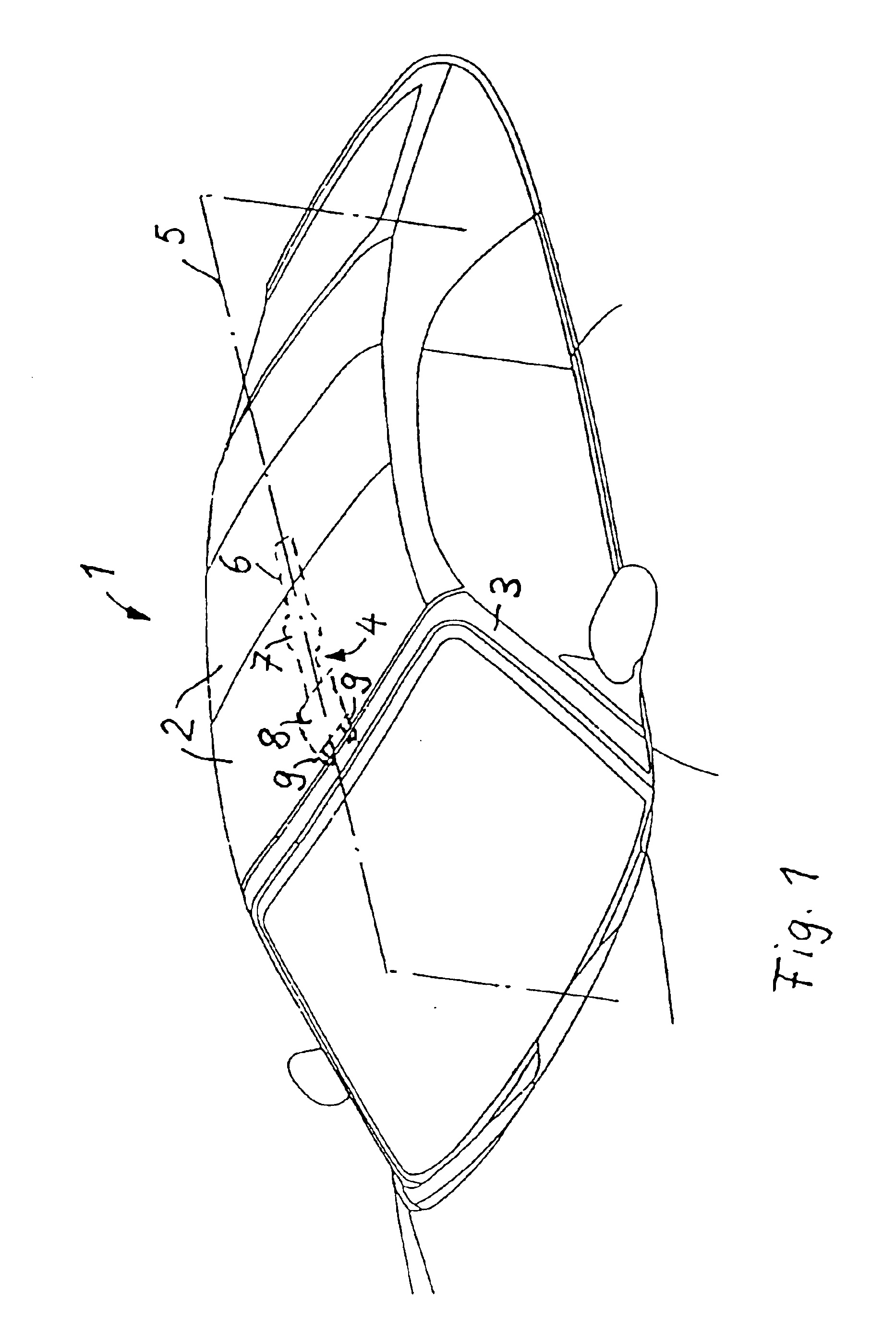
[0019]The vehicle roof 1 as shown in FIG. 1 is movable between a closed position as shown in FIG. 1 and an open position in which the interior of the vehicle is open. The roof comprises a plurality of roof parts 2, which are arranged in the longitudinal direction of the vehicle one behind the other. The vehicle roof 1 is expediently a hardtop with rigid roof parts 2; however it may also be a soft-top with a support linkage on which a roof material is disposed.

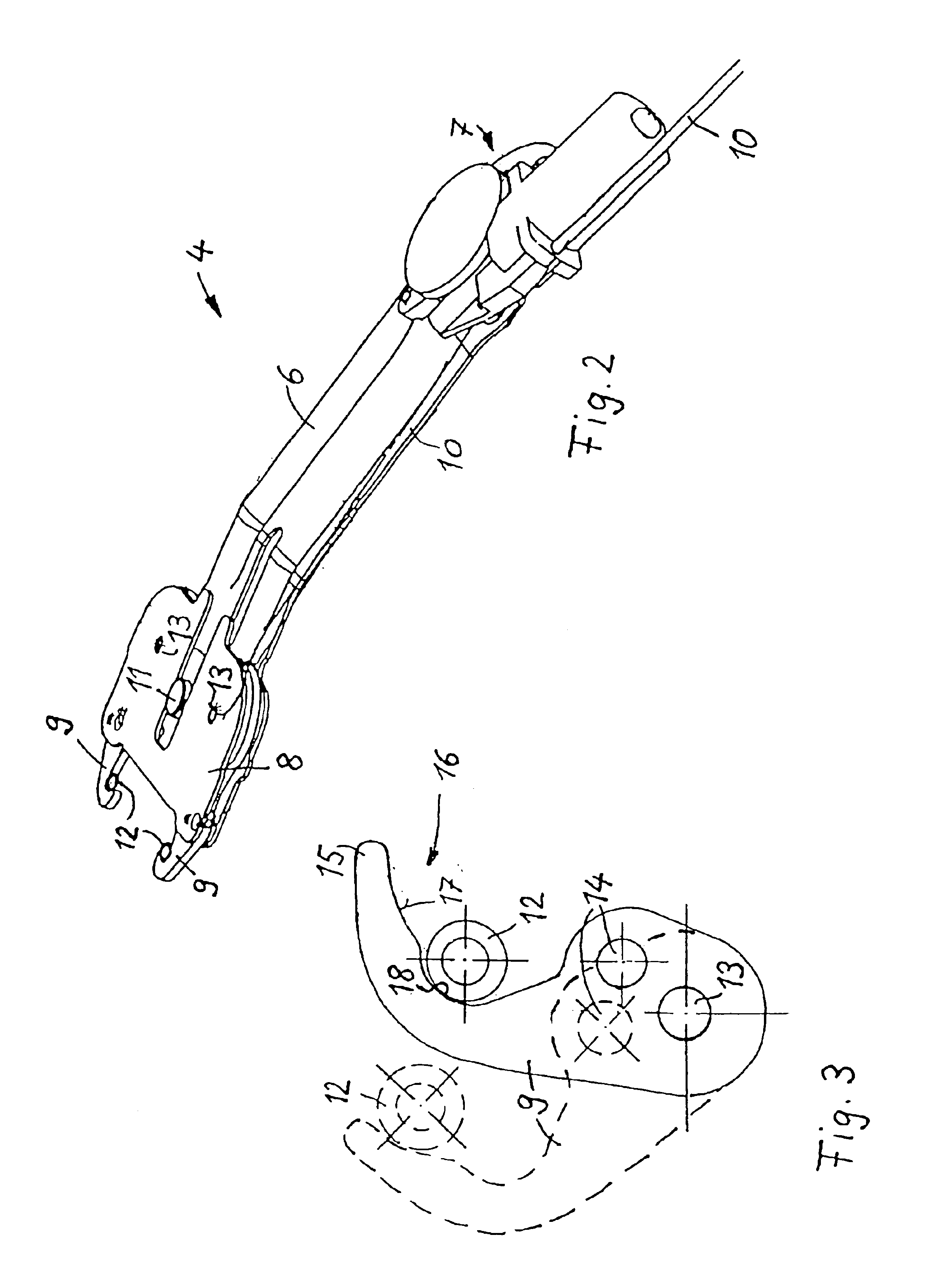
[0020]In order to lock the vehicle roof 1 in its closed position as shown to the windshield frame 3, a locking arrangement 4, which is shown in dashed lines, is arranged on the vehicle roof. The locking arrangement 4 is disposed, symmetrically to a longitudinal center plane 5 of the vehicle, at the inner side of the vehicle roof 1. It consists of a support arm 6, a locking mechanism 26 including an electric mechanical drive 7, a support pla...


PUM


Abstract

In a locking arrangement for a hardtop vehicle roof, which is movable between open and closed positions and includes at least front and rear roof parts, which, in the closed position of the vehicle roof, are disposed behind one another, two locking structures with pivotal locking hooks are supported by support plates on the front roof part for engaging locking pins mounted on a windshield frame and, respectively, the rear roof part and are operable by an operating mechanism so as to pivot toward each other for engaging the locking pins and pulling the roof into firm engagement with the windshield frame, and, at the same time, the front and rear roof parts into firm engagement with each other.

Description

[0001]This is a continuation-in-part application of U.S. patent application Ser. No. 10 / 172,435 filed May 16, 2002 now abandoned.BACKGROUND OF THE INVENTION[0002]The invention relates to a locking arrangement for a hardtop vehicle roof, which is movable between closed and open positions and which includes at least two roof parts arranged, in the longitudinal vehicle direction, behind one another.[0003]WO 96 / 27509 discloses such a locking mechanism by which a multi-part convertible vehicle roof with two roof parts which are disposed in the longitudinal vehicle direction adjacent one another can be locked to the windshield frame when the roof is in a closed position. The locking mechanism comprises a locking hook which is mounted to the front roof part of the removable vehicle roof and a locking pin which is mounted on the windshield frame and which is engaged by the locking hook when the roof is locked in the closed position. The locking hook is rotatably supported by a pivot arm whi...

Claims


Application Information

Patent Timeline
Patent Type & Authority Patents(United States)
IPC IPC(8): B60J7/185B60J7/00
CPCB60J7/1851B60J7/196
Inventor HASSELGRUBER, ANDREASNEUBRAND, FRANKDUSECK, RICHARD
Owner CTS FAHRZEUG DACHSYST
Why Eureka
Try Eureka