Electromechanical parking brake device and electronic system for operating same

a technology of electronic system and parking brake, which is applied in the direction of braking system, axially engaging brake, brake action initiation, etc., can solve the problems of one actuating unit and expensive type, and achieve the effect of convenient operation and reduced expenditur

Active Publication Date: 2016-04-05
LUCAS AUTOMOTIVE GMBH
View PDF53 Cites 5 Cited by
  • Summary
  • Abstract
  • Description
  • Claims
  • Application Information

AI Technical Summary

Benefits of technology

[0010]Therefore not only are economies made on the expenditure for the housing and the installation space of the control unit required in known systems, but also, in particular, the expenditure for electrical contacting between the input unit and the at least one actuating unit is reduced. For it is possible to dispense with an expensive electrical connection between the input unit and the usually customary control unit, since, for example, the input unit and the first control component can be disposed on a common printed circuit board. It is likewise possible to dispense with the electrical connection between the usually customary control unit and the at least one actuating unit, which is likewise of an expensive type in known systems, as it must be designed for the relatively high loads of the electrical actuation mechanism, e.g. electric motor or electromagnet, of the actuating unit.
[0011]It is advantageously possible for the control component which is associated with the input unit to be the control centre of the system which evaluates the driver command and undertakes the corresponding activation (e.g. application or release) of the at least one actuating unit. This “control centre” consequently comprises the computer or microprocessor unit which is now customary in an electronic system and controls and / or regulates the actuating state required for the parking brake device and on which the control or regulating algorithm can be implemented by means of software. As the input unit is in any case located at a location in the vehicle interior which can be conveniently operated by the driver, the computer or microprocessor unit is as a rule accommodated in a protected manner.
[0012]It is likewise advantageously possible for the at least one control component which is associated with the at least one actuating unit to comprise power switches such as transistors, which are required to activate the actuating unit. The control component which is integrated into the input unit therefore has no power switches which subject the input unit to a thermal load, so that no expensive cooling measures are required for this. On the other hand, the additional thermal load which is thereby generated in an actuating unit is to be considered as less critical, as the actuating unit comprises electrical actuation mechanisms which, on account of their relatively high electrical load, generate a considerable amount of heat, for which cooling measures are in any case taken.
[0013]The “outsourcing” or “removal” of the power switches also has the advantage of enabling the electrical connection between the control components of the input unit and the at least one actuating unit to be in the form of “simple” electric lines, as it does not have to be designed for high current loads.
[0015]In some situations it may be expedient to provide redundancy relating to the communication system between the control components. According to one development of this approach, an independent power supply is provided for at least one of the redundantly provided communication systems or one of the redundantly provided communication system parts. This independent power supply is expediently also available when the vehicle is parked. It is thus possible to guarantee re-application of the parking brake even when the ignition is turned off.

Problems solved by technology

It is likewise possible to dispense with the electrical connection between the usually customary control unit and the at least one actuating unit, which is likewise of an expensive type in known systems, as it must be designed for the relatively high loads of the electrical actuation mechanism, e.g. electric motor or electromagnet, of the actuating unit.

Method used


Image

  • Electromechanical parking brake device and electronic system for operating same
  • Electromechanical parking brake device and electronic system for operating same
  • Electromechanical parking brake device and electronic system for operating same

Examples


first embodiment

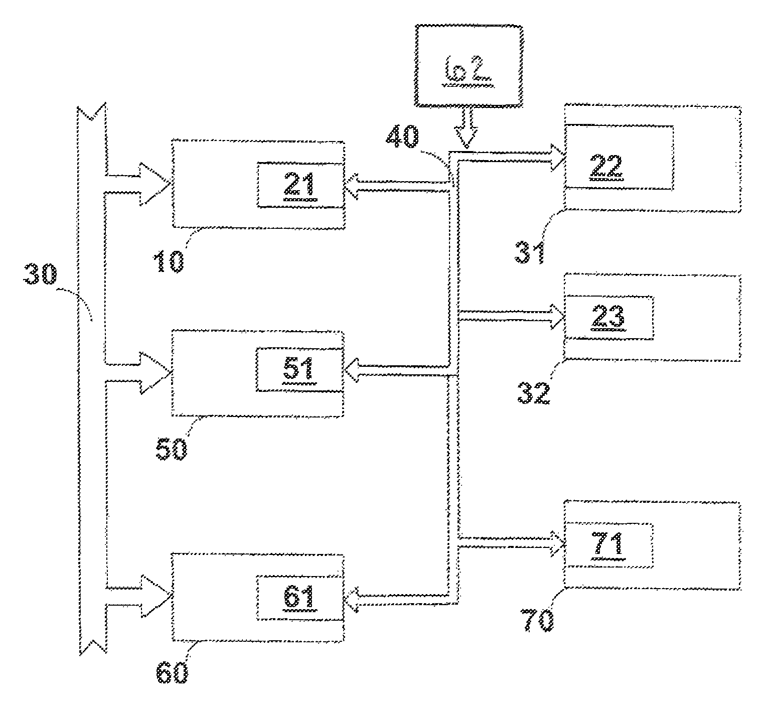
[0019] which is represented in FIG. 1, an electronic control component 21 is integrated into a system unit 10 which may be, for example, an input unit which detects a driver command for actuating the parking brake system by means of a switching means.

[0020]The electronic control component 21, as the so-called “master”, comprises a central computer unit which evaluates the driver command and determines the activation of the parking brake device. For this purpose the electronic control component 21 interacts through data exchange via a communication system 40, e.g. a CAN bus or a LIN bus, with other electronic control components 22 and 23 which are called “slaves” and are integrated into actuating units 31 and 32, which are associated with the brakes of the vehicle. On account of the integration of the electronic control components 22 and 23, the actuating units 31 and 32 thus represent so-called “smart” actuators.

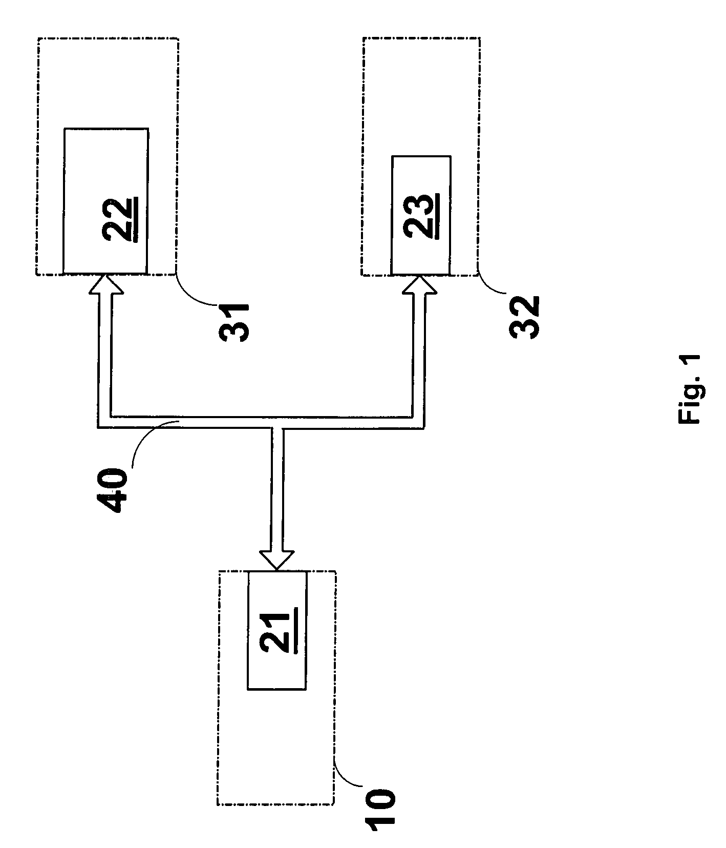
[0021]As compared with the embodiment which is represented in FIG. 1, a...

second embodiment

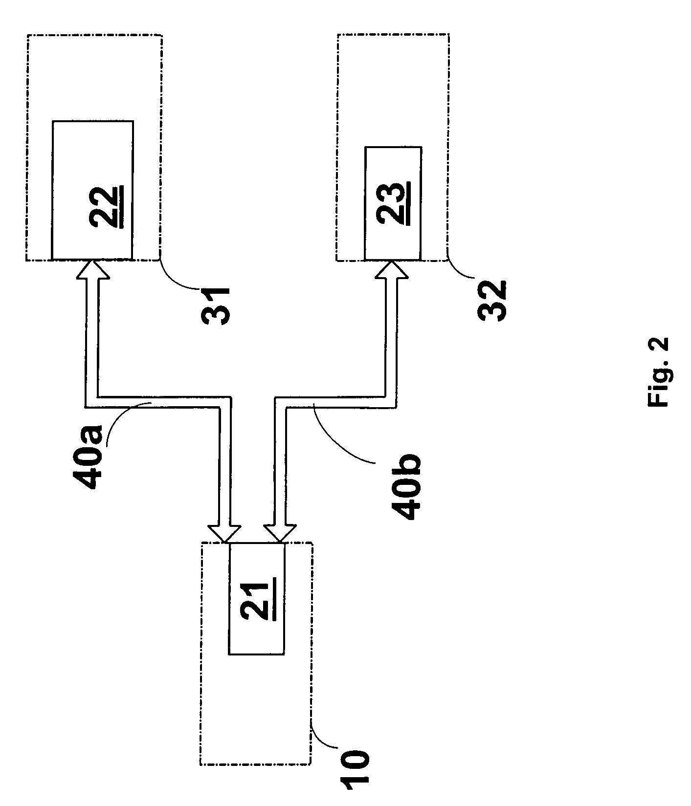
[0022]Broadening the embodiment which is shown in FIG. 2, the embodiment which is shown in FIG. 3 comprises a further system unit 50 with its own electronic control component 51, which interacts via a redundantly formed communication system 40a, 40b with the electronic control components 22 and 23. The redundantly provided communication system parts 40a, 40b are provided parallel to one another, as in the

[0023]The embodiment according to FIG. 3 can be appropriately applied if an actuation of the actuating units 31 and 32 or of the brakes associated with these is also to take place independently of the system unit 10. This is the case, for example, when the system unit 50 is the control unit of an automatic transmission in which, for example, automatic locking of the electromechanical parking brake system takes place in the transmission position marked by “park” or, in brief “P”. This can save expenditure and costs for the usually customary transmission lock (parking lock).

[0024]Acco...


PUM


Abstract

It is proposed, for an electronic system for operating an electromechanical parking brake device of a vehicle with an input unit for detecting a driver command which is evaluated by a control unit which activates at least one actuating unit for actuating at least one brake, that the control unit consist of at least two control components, of which a first control component is associated with the input unit and at least one second control component is associated with the at least one actuating unit.

Description

CROSS-REFERENCE TO RELATED APPLICATIONS[0001]This application is a National Stage of International Application No. PCT / EP2005 / 013532 filed Dec. 9, 2005, the disclosures of which are incorporated herein by reference in entirety, and which claimed priority to German Patent Application No. 10 2004 059 546.1 filed Dec. 9, 2004, the disclosures of which are incorporated herein by reference in entirety.BACKGROUND OF THE INVENTION[0002]The invention relates to an electronic system for operating an electromechanical parking brake device of a vehicle, with an input unit for detecting a driver command which is evaluated by a control unit which activates at least one actuating unit for actuating at least one brake.[0003]An electromechanical parking brake device is known, inter alia, from DE 197 32 168 C1, and corresponding U.S. Pat. No. 6,394,235, both of which are incorporated by reference herein in entirety. A spindle / nut arrangement, which is actuated by an electric motor, serves as the act...

Claims


Application Information

Patent Timeline
Patent Type & Authority Patents(United States)
IPC IPC(8): B60T15/14B60T7/08B60T13/74
CPCB60T7/085B60T13/74
Inventor KOTH, BORISSCHONWALD, BERNDLEITER, RALFGRIESER-SCHMITZ, STEFAN
Owner LUCAS AUTOMOTIVE GMBH
Why Eureka
Try Eureka