Oil seal

a technology of oil seals and seals, applied in the field of oil seals, can solve the problems of wear and tear of oil seals for a long time, and achieve the effect of smooth sliding

Inactive Publication Date: 2005-10-18
KOMATSU LTD
View PDF3 Cites 7 Cited by
  • Summary
  • Abstract
  • Description
  • Claims
  • Application Information

AI Technical Summary

Benefits of technology

[0008]An object of the present invention is to provide a two-liquid-sealing oil seal that can improve sealability and durability.

Problems solved by technology

However, since the oil seal is used making contact with a rotary shaft, it is likely to wear on account of a use condition including a rotational speed and a temperature, and accordingly, the development of a material which is excellent in wear-resistance is desired.
Particularly, since the radial seal lip abutted from the radial direction of the rotary shaft needs the surface pressure in some measure against the rotary shaft for preferably sealing around the rotary shaft, it is likely to wear with use for a long time.

Method used


Image

  • Oil seal
  • Oil seal
  • Oil seal

Examples


Embodiment Construction

)

[0032]An embodiment of the present invention will be described below with reference to attached drawings.

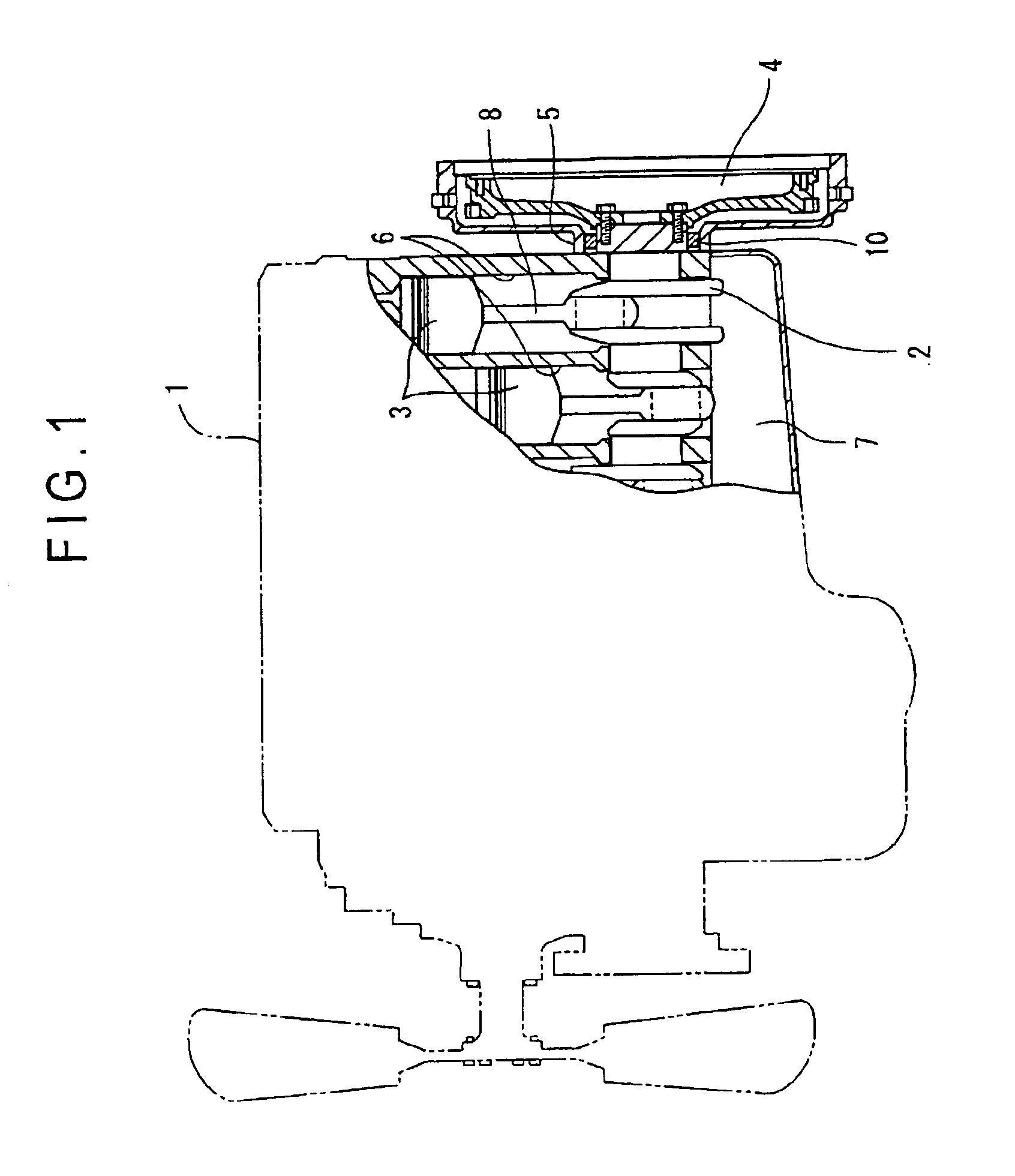
[0033]FIG. 1 is a partly sectioned view showing an engine 1 according to this embodiment.

[0034]In FIG. 1, the engine 1 incorporates a plurality of cylinders 6 formed therein, a plurality of pistons 3 which receive a pressure of combustion gas in the respective cylinders 6 so as to reciprocate therein, a crank shaft (rotary shaft) 2 for converting the reciprocating motion of the pistons 3 into a rotary motion. Each piston 3 is coupled to the crank shaft 2 mutually arranged in parallel through the intermediary of connecting rods 8, respectively, so as to be reciprocatable.

[0035]Engine oil as lubrication oil is fed to slide parts between the cylinders 6 and the pistons 3 and between the pistons 3 and the crank shaft 2. The engine oil is reserved in an oil pan 7 provided in the lower part of the engine, and is sucked up by an oil pump (not shown) or the like. Thereafter, the engine ...


PUM


Abstract

An oil seal (10) includes a first seal (20) for sealing an engine (1) side and a second seal (30) for sealing a flywheel (4) side. The first seal (20) is an axial seal abutted on an inner ring (11) from the direction along the axial direction of a crank shaft (2). The second seal (30) is a radial seal abutted on the inner ring (11) from the direction along the radial direction of the crank shaft (2). A communication hole (25) is provided on the second seal (30), thereby preventing a space (40) surrounded by the first seal (20), the second seal (30) and the inner ring (11) from the occurrence of the negative pressure.

Description

BACKGROUND OF THE INVENTION[0001]1. Field of the Invention[0002]The present invention relates to an oil seal, and in particular to a two-liquid-sealing oil seal in which liquid present on both sides of the oil seal are sealed.[0003]2. Description of Related Art[0004]Conventionally known oil seals include a one-liquid-sealing oil seal having a single lip for preventing lubrication oil around a rotary shaft from leaking from one side to the other side of the oil seal, and a two-liquid-sealing oil seal having lips provided on both sides of the oil seal for preventing lubrication oils present on both sides from leaking from one side to the other side or vise versa. The two-liquid-sealing oil seal is provided, for example, between the outer circumference of a crank shaft of an engine and the inner circumference of a flywheel housing in order to seal engine oil fed on the crank shaft and lubrication oil fed on a clutch disc on the flywheel side or a transmission.[0005]The two-liquid-seali...

Claims


Application Information

Patent Timeline
Patent Type & Authority Patents(United States)
IPC IPC(8): F16J15/16F16J15/32F16J15/34F16J15/3228
CPCF16J15/164F16J15/3256F16J15/3456
Inventor IWAKATA, KEISAKUMIHARA, KENJI
Owner KOMATSU LTD
Why Eureka
Try Eureka