Illuminated pole-suspended flag and method of illuminating

a technology of illuminated poles and flags, applied in the direction of lighting and heating apparatus, lighting support devices, instruments, etc., can solve the problems of sky glow, glare, sky glow and other types of light pollution, and waste one billion dollars annually to generate light, so as to achieve the effect of reducing the increase of night sky light pollution

Inactive Publication Date: 2005-10-18
SCHROEDER KARL S
View PDF5 Cites 26 Cited by
  • Summary
  • Abstract
  • Description
  • Claims
  • Application Information

AI Technical Summary

Benefits of technology

[0006]To enable legal twenty-four hour national flag display, to permit night display of vehicle-mounted school and team flags, and to do either with minimal increase in night sky light pollution, I mount a light source immediately adjacent a flag and direct the light essentially directly toward the flag, rather than upwardly into the sky. Preferably, the light source is provided within a transparent portion of the flag-mounting pole, and is ideally focused directly toward the flag by a reflector which is adapted to shift positions with changes in flag positions due to directional changes of air flow across the flag.

Problems solved by technology

Pole-mounted flags present a not-insignificant problem of atmospheric light pollution when the flag is on a tall pole or flagstaff and one or more spotlights at ground level are focused on the flag area surrounding 360 degrees at the top of the pole.
According to the International Dark-Sky Association, over one billion dollars is wasted annually to generate light that does nothing more than light up the sky unnecessarily, and create problems while doing so.
It is estimated that almost one third of the light created out-of-doors escapes into the night sky where, instead of providing useful illumination, it causes glare, sky glow and other types of light pollution.
While the most common causes of light pollution are street lights, security lights, billboards lit from below, landscape illumination directed upwardly, businesses like convenience stores and gas stations that operate under extremely high levels of illumination, spot lights trained on night-lit flags also contribute to some extent to the overall problem.

Method used


Image

  • Illuminated pole-suspended flag and method of illuminating
  • Illuminated pole-suspended flag and method of illuminating
  • Illuminated pole-suspended flag and method of illuminating

Examples


Embodiment Construction

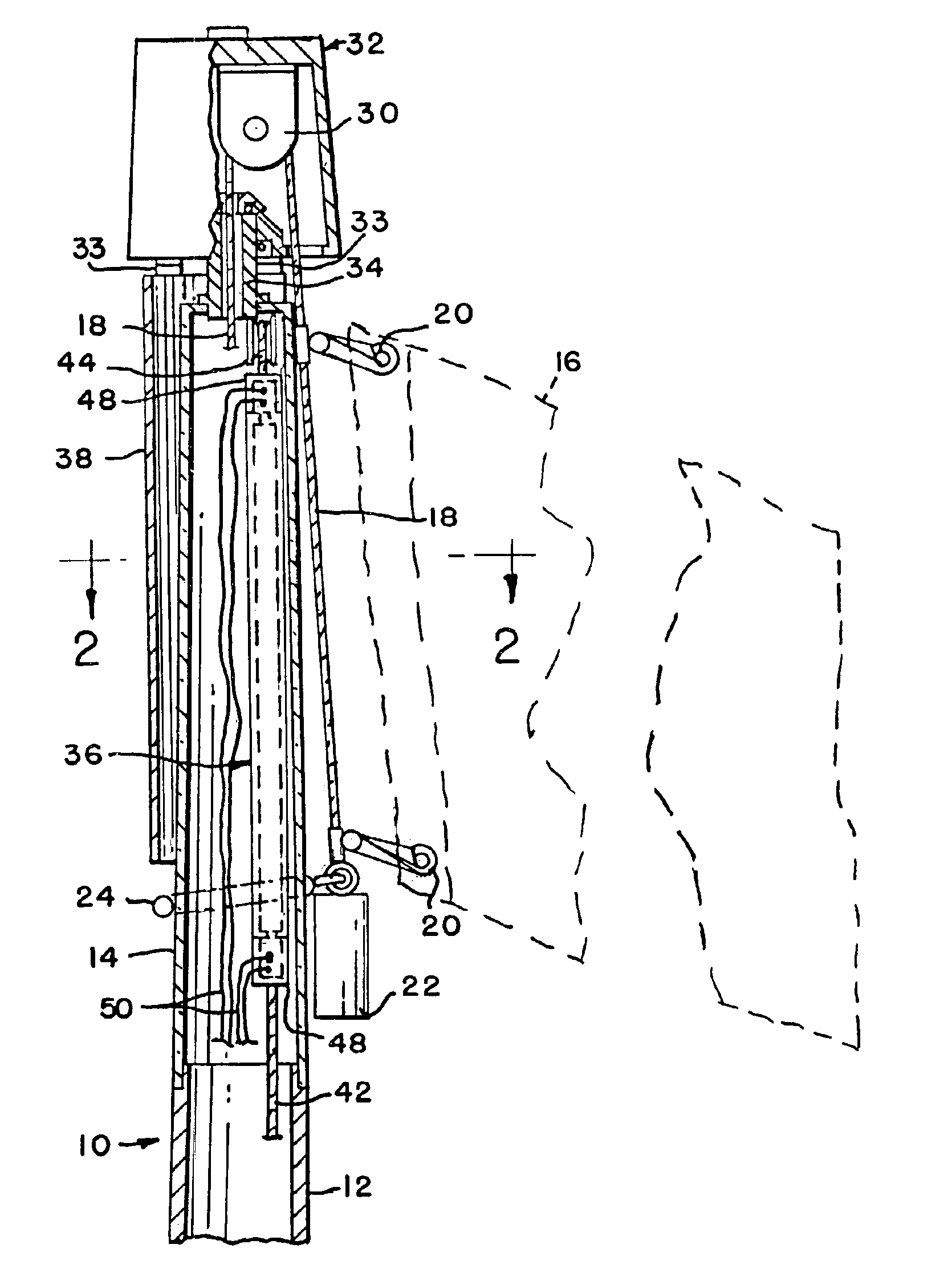
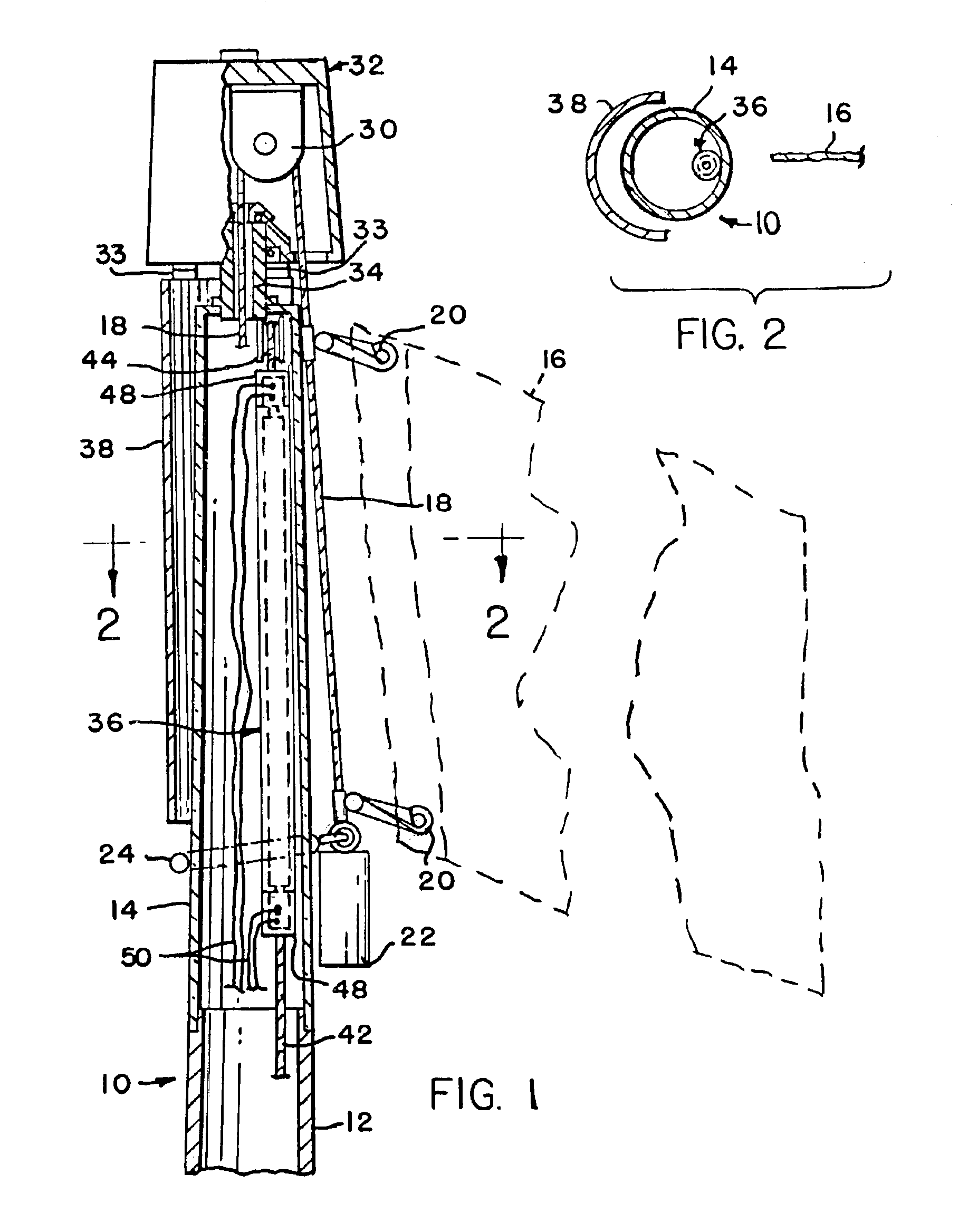
[0019]FIG. 1 shows the upper or top section of a permanent flagpole 10 having a metallic tubular portion 12 for its principal length and a transparent plastic tubular portion 14 mounted atop the portion 12. The portion 14 is of a length at least somewhat exceeding the height of a flag 16. Portion 14 securely interfits the portion 12 in a manner providing a smooth continuation of the exterior surface of the two tubular portions. While FIG. 1 shows the flagpole 10 as being vertical and may be referred to in that manner, it should be understood that the flagpole 10 may be angled and may be either ground or building mounted.

[0020]The left end of flag 16 is suspended from a line or halyard 18 by any means such as swivel hooks 20 applied to the halyard 18. In addition, a counterweight 22 and a beaded retainer ring 24 may be supported at the extended end of the halyard 18 to maintain the suspended end of the halyard 18 and flag 16 taut and closely adjacent the flagpole. The remote end of t...


PUM


Abstract

To enable legal twenty-four hour national flag display, to permit night display of vehicle-mounted school and team flags, and to do either with minimal increase in night sky light pollution, I mount a light source immediately adjacent a flag and direct the light essentially directly toward the flag, rather than upwardly into the sky. Preferably, the light source is provided within a transparent portion of the flag-mounting pole, and is ideally focused directly toward the flag by a reflector which is adapted to shift positions with changes in flag positions due to directional changes of air flow across the flag.

Description

[0001]This application is based on U.S. Provisional Patent Application Ser. No. 60 / 371,565 filed Apr. 11, 2002.[0002]This invention relates to flag illumination from immediately adjacent a flag under night or low light conditions, whether such flag is mounted on a stationary flagpole, on a moving vehicle or is hand carried.BACKGROUND OF THE INVENTION[0003]Chapter 10 of Title 36 of the United States Code recommends American flag display only from sunrise to sunset. However, it also states that American flags “may be displayed twenty-four hours a day if properly illuminated during hours of darkness”. Flags, particularly national flags and team or school flags, represent a source of pride to those who display them. University flags are frequently quite prominently exhibited on vehicles traveling to and from major sporting events of the school. It is fair to assume that if school flags could be easily and inexpensively lit up after dark, many would opt for the added feature.[0004]Pole-m...

Claims


Application Information

Patent Timeline
Patent Type & Authority Patents(United States)
IPC IPC(8): G09F17/00
CPCG09F17/00
Inventor SCHROEDER, KARL S.
Owner SCHROEDER KARL S
Why Eureka
Try Eureka