Cartridge style fluid dynamic bearing with conical or spherical bearing elements

a technology of fluid dynamic bearings and bearing elements, which is applied in the direction of bearings, shafts and bearings, rotary bearings, etc., can solve the problems of poor resistance to operating shock and vibration, wear, run-out and manufacturing difficulties, and many mechanical problems of ball bearing assemblies

Inactive Publication Date: 2005-10-18
SEAGATE TECH HDD HLDG +3
View PDF4 Cites 9 Cited by
  • Summary
  • Abstract
  • Description
  • Claims
  • Application Information

AI Technical Summary

Benefits of technology

[0008]The present invention provides a fluid dynamic bearing cartridge where the bearing is defined between two relatively rotating surfaces which are open to the air at both ends, thereby allowing the use of a fixed shaft or sleeve.

Problems solved by technology

However, ball bearing assemblies have many mechanical problems such as wear, run-out and manufacturing difficulties.
Moreover, resistance to operating shock and vibration is poor, because of low damping.
The problem with such conventional capillary seals is that they depend entirely on surface tension to maintain or draw fluid back into the motor.
However, such capillary seals have been shown to be quite weak and have low volume.
The problem with this low stiffness in a motor open at two ends is that only a small pressure imbalance in the motor can overcome the low seal stiffness, and cause oil to be lost with larger seal volume, the seal reservoir can store oil for equalization purposes.

Method used


Image

  • Cartridge style fluid dynamic bearing with conical or spherical bearing elements
  • Cartridge style fluid dynamic bearing with conical or spherical bearing elements
  • Cartridge style fluid dynamic bearing with conical or spherical bearing elements

Examples


Embodiment Construction

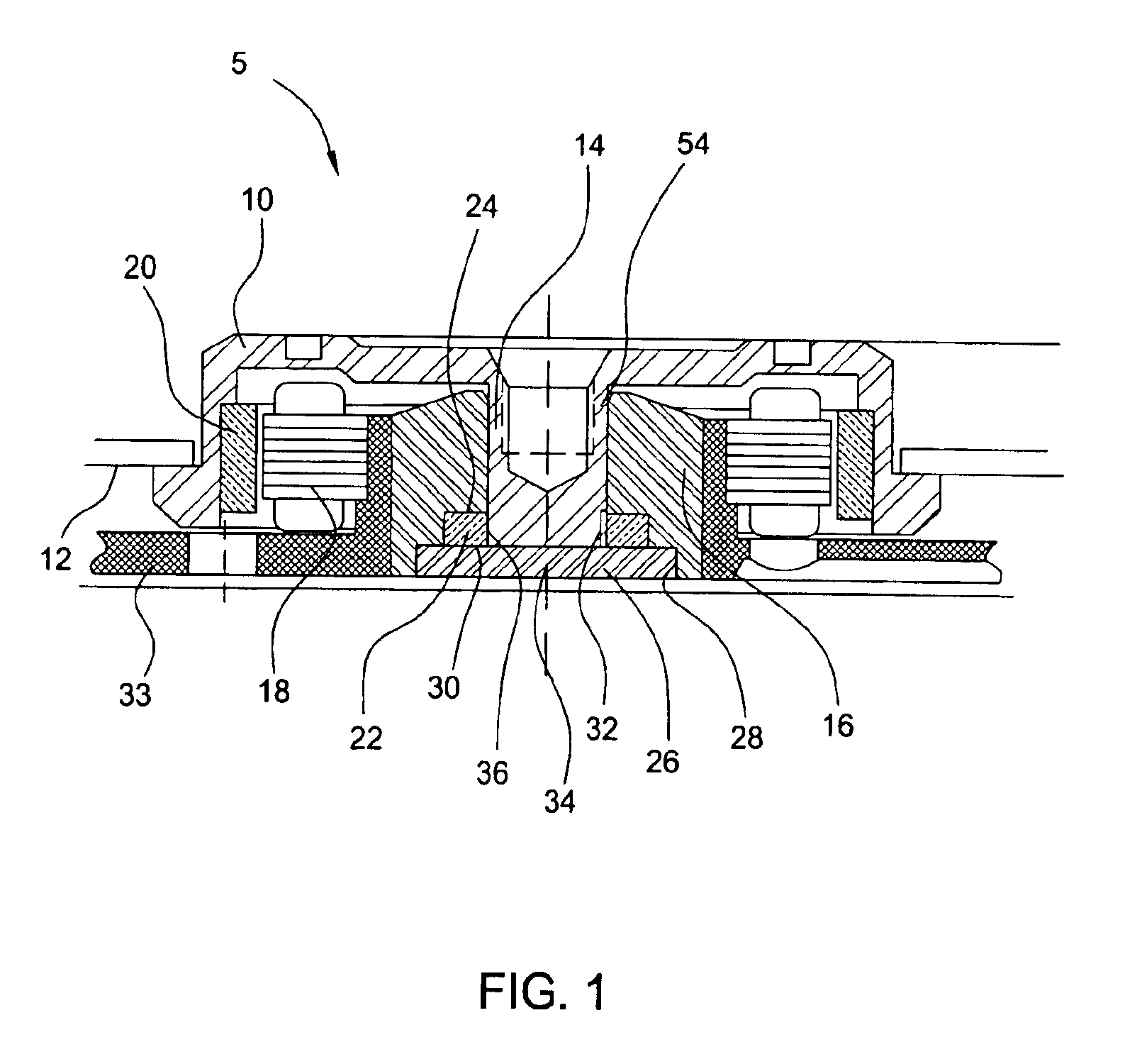
[0018]The present invention will next be described with respect to the following figures. This application will disclose in detail an embodiment of the capillary seal and grooved pumping seal utilized in the cartridges of this invention. Details of several of the structural elements which appear herein can also be found by referring to the cited co-pending patent applications which are incorporated herein by reference. The arrangement of one or more of these seals to support a shaft sleeve or cylinder, preferably in a balanced pressure environment in which the fluid is reliably contained within a cartridge, will then be described with reference to the following figures.

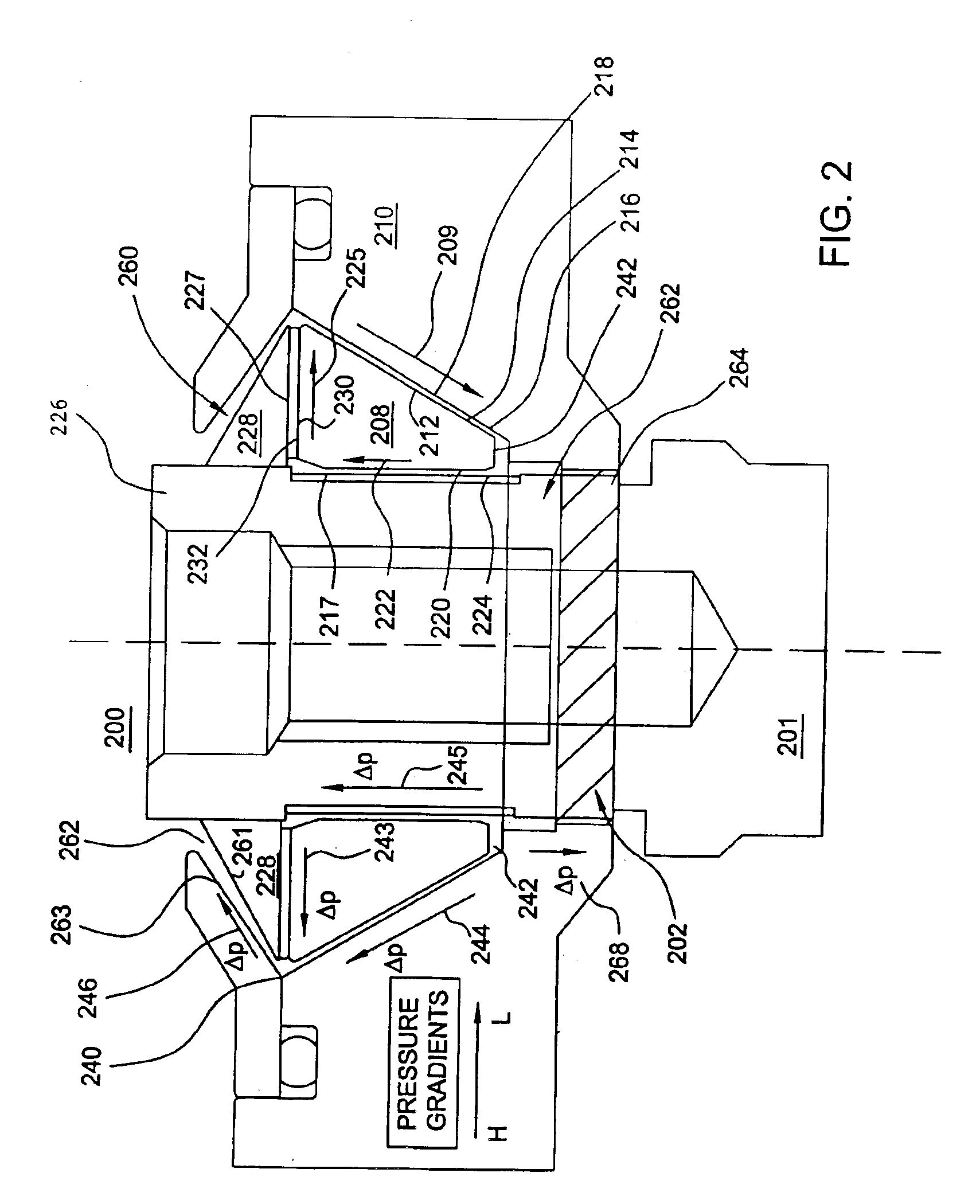
[0019]Referring next to FIG. 2, the sealing designs shown in this figure provide a very positive sealing means for fluid dynamic bearing cartridges. The two seals are shown operating in combination; however, they may be used separately, in combination with certain other forms of hydrodynamic bearings. The centrifugal ...


PUM


Abstract

A fluid dynamic bearing cartridge includes a shaft or sleeve adapted to be fixed in place has at least one fluid dynamic bearing supporting the shaft and one or more seals at either end of the shaft. The seal arrangements may include a pair of centrifugal capillary seals at either end of the shaft. Alternatively, a grooved pumping seal or centrifugal capillary seal at one end may be used in combination with a static capillary seal, especially where a journal bearing defined along the shaft near the capillary seal has an imbalanced groove section.

Description

[0001]This divisional application claims priority to U.S. application Ser. No. 09 / 595,295 filed Jun. 15, 2000 now U.S. Pat. No. 6,655,841.CROSS-REFERENCE TO RELATED APPLICATION[0002]This application extends and modifies the principles taught in U.S. application Ser. No. 09 / 060,328 filed Apr. 14, 1998 (A-65481) and U.S. application Ser. No. 09 / 060,342 filed Apr. 14, 1998 (A-65485), assigned to the assignee of this invention and incorporated herein by reference.FIELD OF THE INVENTION[0003]The present invention is related to a fluid dynamic bearing incorporated into a cartridge.BACKGROUND OF THE INVENTION[0004]The stability and lifetime of a shaft and a sleeve and bearing assembly is of critical importance. One typical bearing assembly comprises ball bearings supported between a pair of races which allow relative rotation of the inner and outer pieces. However, ball bearing assemblies have many mechanical problems such as wear, run-out and manufacturing difficulties. Moreover, resistan...

Claims


Application Information

Patent Timeline
Patent Type & Authority Patents(United States)
IPC IPC(8): F16C33/04F16C33/10F16C17/00F16C17/10
CPCF16C17/026F16C17/10F16C33/107F16C17/105
Inventor HEINE, GUNTERGRANTZ, ALAN LYNDON
Owner SEAGATE TECH HDD HLDG
Why Eureka
Try Eureka