Electrically blockable swiveling lever control

a technology of swivel lever and actuating mechanism, which is applied in the direction of mechanical control device, wing knob, keyhole guard, etc., can solve the problems of uneconomical for many applications

Inactive Publication Date: 2006-08-15
DIRAK DIETER RAMSAUER KONSTRUKTIONSELEMENTE GMBH & CO KG
View PDF20 Cites 24 Cited by
  • Summary
  • Abstract
  • Description
  • Claims
  • Application Information

AI Technical Summary

Benefits of technology

[0006]It is the primary object of the invention to modify the electrically lockable swivel lever actuating mechanism of the type mentioned above in such a way that it is constructed in a simple manner and, in particular, requires no special devices that are constructed on the door frame or the like instead of on the door leaf or the like.

Problems solved by technology

This is uneconomical for many applications.

Method used


Image

  • Electrically blockable swiveling lever control
  • Electrically blockable swiveling lever control
  • Electrically blockable swiveling lever control

Examples


Embodiment Construction

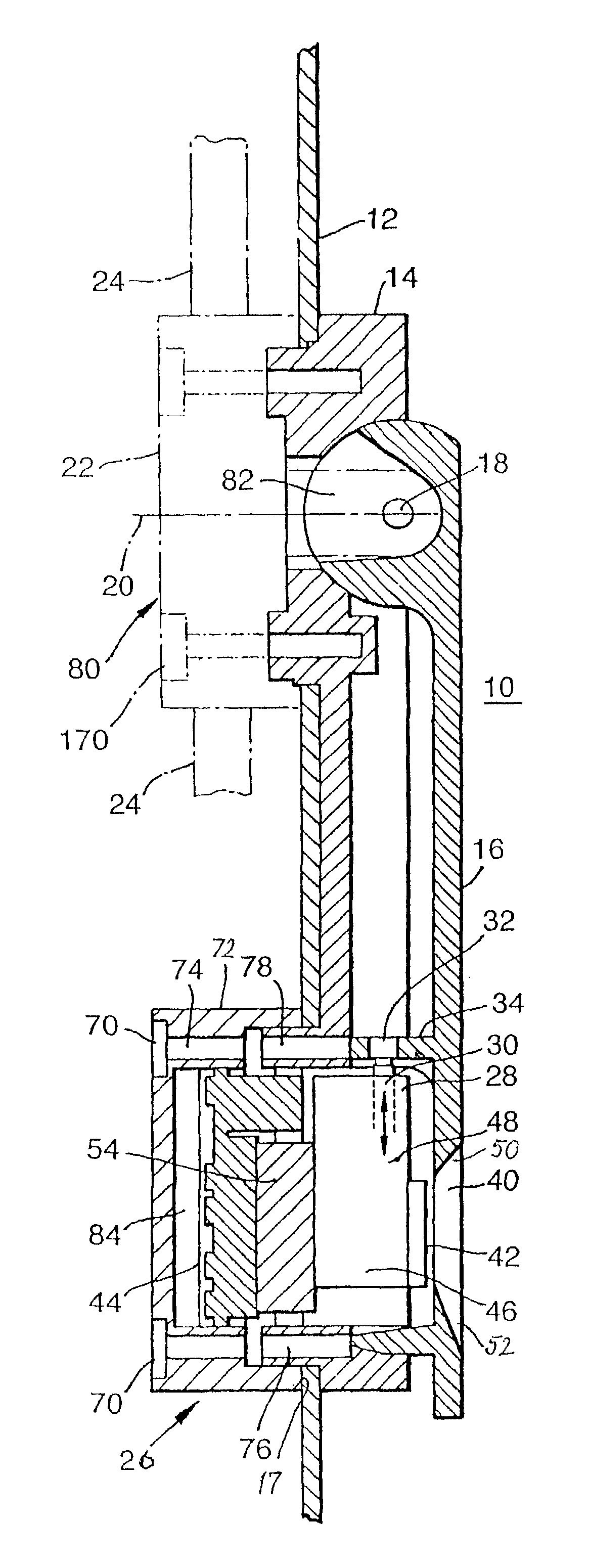
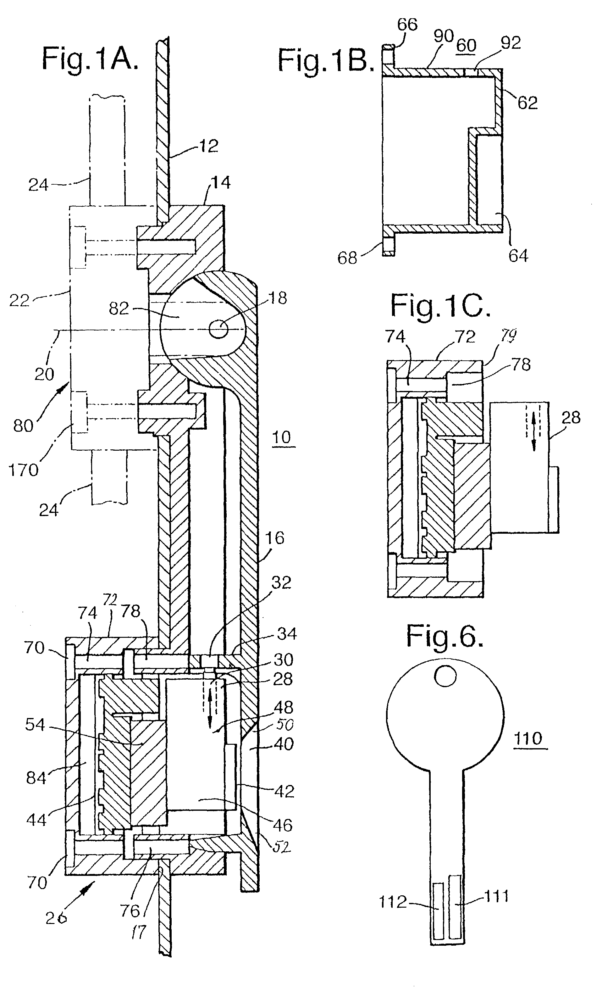
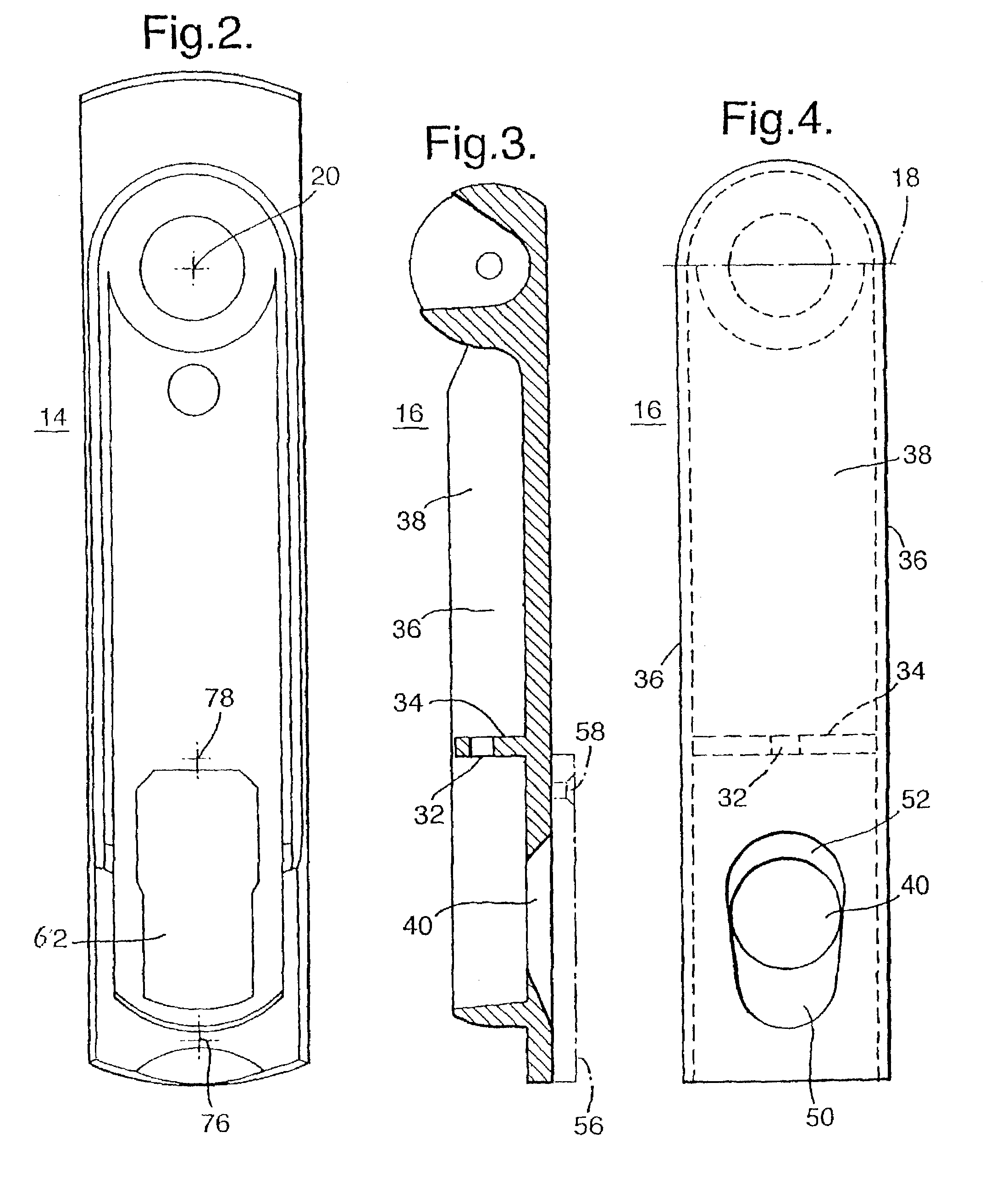
[0043]FIG. 1A shows an electrically lockable swivel lever actuating mechanism 10 comprising a dish 14 which can be placed on a door leaf 12 or the like. An actuation lever 16 is mounted in the dish 14 in such a way that from a position in which it is swiveled out of the dish (see swivel-out axis 18) and in which actuation of the closure actuation is made possible, e.g., by rotating the swiveled out hand lever 16 about the axis 20, e.g., of a ribbon bar lock casing 22, during which rotation, for example, ribbon bars 24 mounted in the lock casing 22 are pushed outward, a door leaf in a frame, for example, is unlocked in a manner known per se (see prior art) during this pushing outward. Conversely, when the actuation lever 16 is in the swiveled in position shown in FIG. 1A, actuation of the closure is not possible. An electromechanical lock device which holds the swivel lever 16 in its swiveled in position serves to secure the hand lever and, therefore, the closure in this position.

[00...


PUM


Abstract

The description relates to a closure for mounting in an opening in a thin wall, such as a sheet metal cabinet door, which comprises a housing and which has, at one end, a bearing support for an actuation lever and, at its other end, a lock device for the actuation lever and a fastening device such as a clamping clip therebetween. The housing has a partially spherical bearing surface with a cylindrical bore hole proceeding from it, wherein a partial ball with a first bearing for a closure drive shaft extending through the cylindrical bore hole and with a second bearing for the actuation lever is arranged in the cylindrical bore hole, and the two bearings enable a rotation of the partial ball in relation to the housing and a swiveling of the actuation lever in relation to the partial ball around an axis vertical to the closure drive shaft and to the extension of the lever.

Description

CROSS-REFERENCE TO RELATED APPLICATIONS[0001]This application claims priority of PCT Application Ser. No. PCT / EP01 / 01486, filed Feb. 10, 2001 and German Application No. 200 06 373.1, filed Apr. 6, 2000, the complete disclosures of which are hereby incorporated by reference.BACKGROUND OF THE INVENTION[0002]a) Field of the Invention[0003]The invention is directed to an electrically lockable swivel lever actuating mechanism comprising a dish which can be placed on a door leaf or the like and in which an actuation lever for a closure, such as a sash closure or bar closure, is mounted in such a way that it can be moved out of a position in which it is swiveled out of the dish and in which it enables actuation of the closure into a position in which it is swiveled into the dish and in which it does not allow actuation of the closure and in which it can be locked by an electromechanical lock device.[0004]b) Description of the Related Art[0005]A swivel lever actuating mechanism of the type ...

Claims


Application Information

Patent Timeline
Patent Type & Authority Patents(United States)
IPC IPC(8): E05B13/10E05B1/00E05B5/02E05B17/18E05B17/22E05B47/06G07C9/00
CPCE05B47/0657E05B17/22E05B1/0092E05B17/185E05B17/186Y10S292/31E05B47/0012G07C2009/00793Y10T70/5761Y10T70/7102Y10T70/577Y10T292/85Y10T70/7068
Inventor RAMSAUER, DIETERPETERSEN, VOLKHARD
Owner DIRAK DIETER RAMSAUER KONSTRUKTIONSELEMENTE GMBH & CO KG
Why Eureka
Try Eureka