
Prosthetic femoral joint

a femoral joint and prosthesis technology, applied in the field of prosthetic femoral joints, can solve the problems of wear, wear, and wear of deformable materials, and achieve the effects of reducing wear and wear risk, reducing wear and tear risk, and improving wear resistan

Active Publication Date: 2009-04-21
STRYKER EURO OPERATIONS HLDG LLC
View PDF33 Cites 25 Cited by
  • Summary
  • Abstract
  • Description
  • Claims
  • Application Information

AI Technical Summary

Benefits of technology

[0006]An advantage of this construction is that some standard sized ball heads can be used. The entry into the cup can be closely controlled by the dimensions of the flat on the inner bearing surface so that the operation of the ball head against the bearing surface is accurate.

Problems solved by technology

A deformable material cannot be used and in a first arrangement a ring or circlip is used but this requires a third part and there is risk of wear.
A disadvantage with this type of construction is that specific heads are required and there is the risk of wear due to the truncating of the head.

Method used


Image

  • Prosthetic femoral joint
  • Prosthetic femoral joint
  • Prosthetic femoral joint

Examples


Embodiment Construction

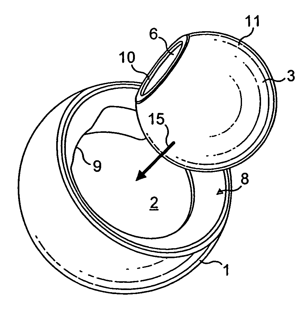
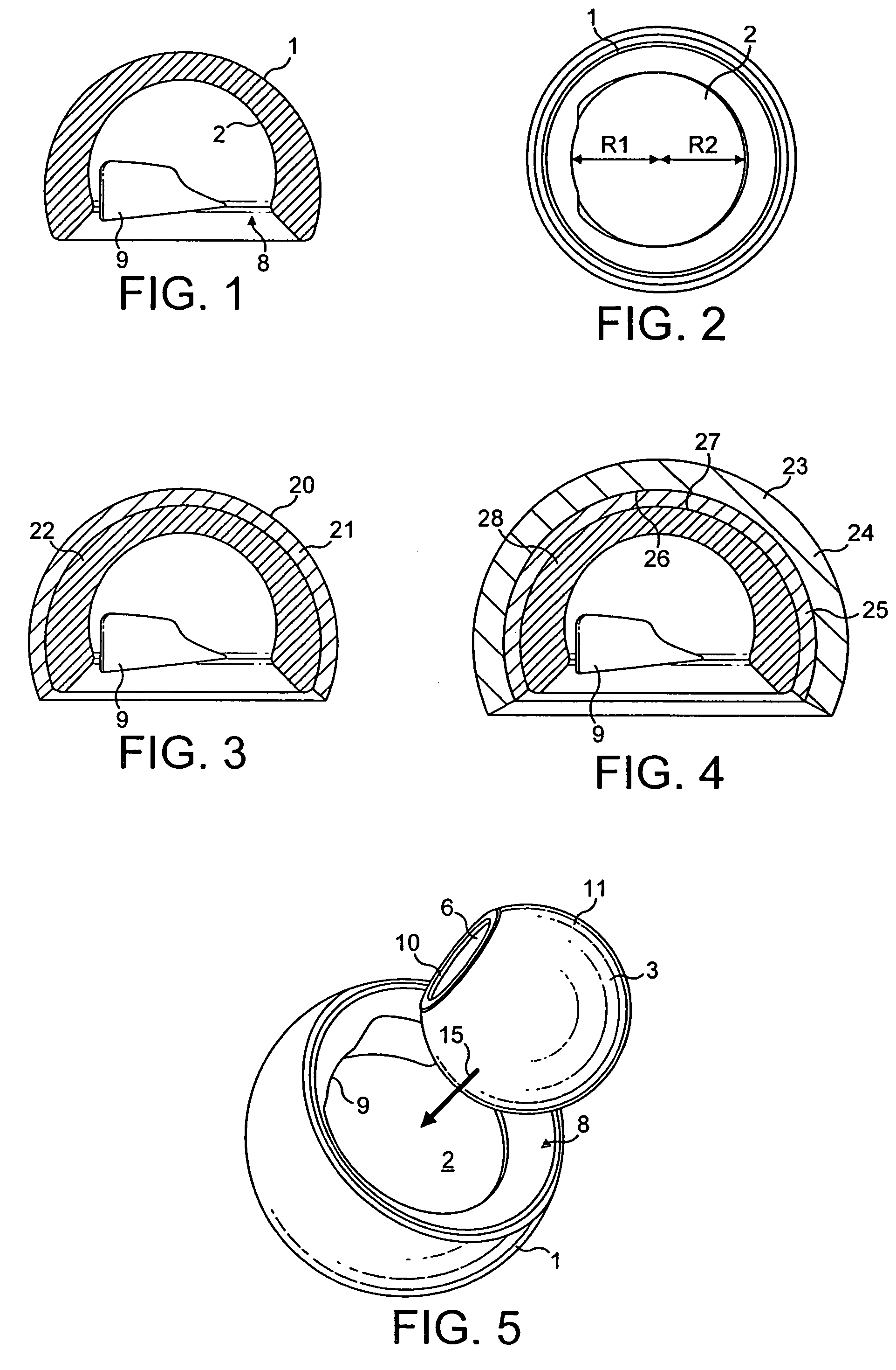
[0025]FIGS. 1 and 2 show the application of the invention to a prosthetic femoral joint which comprises a part-spherical cup 1 which is made from a single material, for example a synthetic plastics material such as ultra-high molecular weight polyethylene, and which is adapted for location in an acetabulum. The cup 1 has a part-spherical inner bearing surface 2 to receive a part-spherical ball head 3 (see FIG. 5) which can be attached to a stem 4 (see FIG. 8) for location in a femur. The stem 4 has a shoulder carrying a tapered spigot 5 which is adapted to locate and be retained in a tapered socket 6. This method of attachment is well-known and the construction of the stem and spigot are also well-known in themselves and will not be described further.

[0026]As will be seen from FIG. 1, the inner bearing surface 2 of the cup extends around an angle of more than 180° i.e. below the equator and a portion thereof adjacent an entry mouth 8 is formed with a substantially flat face 9 which ...


PUM


Abstract

A prosthetic hip joint replacement system has a femoral component with a tapered trunion thereon. A modular head with a part-spherical outer surface terminating in a planar surface, engages the trunion. An acetabular cup member is provided for receiving the part-spherical head of a femoral implant, the cup member has a cavity having a part-spherical inner surface for receiving the modular head. The part-spherical inner surface of the cup defines a polar axis and an equator centered about a pole of the cavity. The cavity has a part-circular opening spaced from the pole a greater distance than the equator. Thus the inner part-spherical bearing surface extends beyond the 180° which the equator extends. The configuration of the part-spherical inner bearing surface causes a movement of translation of the head during rotation so that there is a crescent shaped retention area on each opposed side thereof. The opening has a non-circular or planar portion alignable with the planar head surface during insertion of the head in the cavity and a plane parallel to the non-circular portion through the center of the portion of the opening being offset from a parallel plane containing the polar axis of the cavity.

Description

BACKGROUND OF THE INVENTION[0001]This invention relates to a prosthetic femoral joint which comprises a part-spherical cup adapted for location in an acetabulum and having a part-spherical inner bearing surface to receive a part-spherical ball head which can be attached to a stem for location in a femur and in which the inner bearing surface of the cup extends around an angle of more than 180°. Cups of this type are known which comprise a single element made, for example, of a synthetic plastics material or metal. The inner bearing surface can also be formed on an insert which again can be of a synthetic plastics material, a ceramic, or a metal and which is carried in an outer housing or shell, the housing engaging the acetabulum with which it is to be used and being held in place by, for example, cement or by mechanical means, for example nails or screws. The cup is used in connection with Total Hip Arthroplasty which includes implanting a femoral component in the femur which compo...

Claims


Application Information

Patent Timeline
Patent Type & Authority Patents(United States)
IPC IPC(8): A61F2/32A61F2/00A61F2/30A61F2/34A61F2/36A61F2/46
CPCA61F2/32A61F2002/30332A61F2002/30604A61F2002/30612A61F2002/30937A61F2002/3208A61F2002/3233A61F2002/3446A61F2002/3448A61F2002/345A61F2002/3493A61F2002/3611A61F2002/3625A61F2002/365A61F2002/4631A61F2220/0033A61F2310/00011A61F2310/00179
Inventor DELOGE, NICOLASAUXEPAULES, ARNAUD
Owner STRYKER EURO OPERATIONS HLDG LLC
Learn More