Remote maintenance system

a maintenance system and remote technology, applied in data switching networks, program control, instruments, etc., can solve problems such as failure decisions, heavy load on the center server, and difficult for the home server to make accurate failure decisions

Inactive Publication Date: 2004-08-03
PANASONIC CORP
View PDF3 Cites 128 Cited by
  • Summary
  • Abstract
  • Description
  • Claims
  • Application Information

AI Technical Summary

Benefits of technology

is to provide a remote maintenance system that can make a failure diagnosis in touch with actual conditions such as usage environment of each electrical appliance by holding a latest failure model in a home server all the time. Also, the second object of the present invention is to display failure information of the appliance in a manner corresponding to a viewer's needs.
In other words, the home server in the remote maintenance system of the present invention decides whether an electrical appliance has failed or not using the latest failure model updated in the center server. As a result, there is an effect that the home server can make a failure diagnosis in touch with the actual conditions of each electrical appliance, such as secular changes and usage environments, because the center server updates the failure model based on the status information of the electrical appliance which has been collected from each house.
Therefore, according to the remote maintenance system of the present invention, different contents of failure information can be displayed on the customer display unit in the home server and the serviceman display unit in the center server. In other words, on the customer display unit, failure and repair information can be displayed in a plain expression for a customer instead of technical and detailed information about an electrical appliance and the repair which seems to be unnecessary to the customer. As a result, referring to the customer display unit can prevent a wrong action of the customer when he / she finds trouble with the electrical appliance. Further, since technical, on-target and more detailed repair information can be displayed on the serviceman display unit for a serviceman, there is an effect that he / she can take appropriate measures against a failure of the electrical appliance efficiently and quickly even without any special repair skill or experience.

Problems solved by technology

However, there is a disadvantage that a load on the center server becomes heavy when the center server makes failure decisions of many kinds of electrical appliances located in each house in a centralized manner.
In other words, if the home server of each house holds a failure model corresponding to all models of the electrical appliances located there, it can make this failure decision.
However, there is a problem in the conventional failure model, which is configured basically based on fixed reference values.
That is, when the state of the appliance varies from the initial state due to secular changes or usage environment of each house, it becomes difficult for the home server to make an accurate failure decision, and it may decide that an apparatus has failed during normal operation or decide that the appliance is normal in spite of a failure, for example.
Although the information such as a part name inside the appliance, a name of a replacement part for repair, a product number code, a failure code, etc. is very useful for the serviceman who is going to repair the electrical appliance, display of such unfamiliar information is meaningless and inconvenient for the customer.

Method used


Image

  • Remote maintenance system
  • Remote maintenance system
  • Remote maintenance system

Examples


Embodiment Construction

)

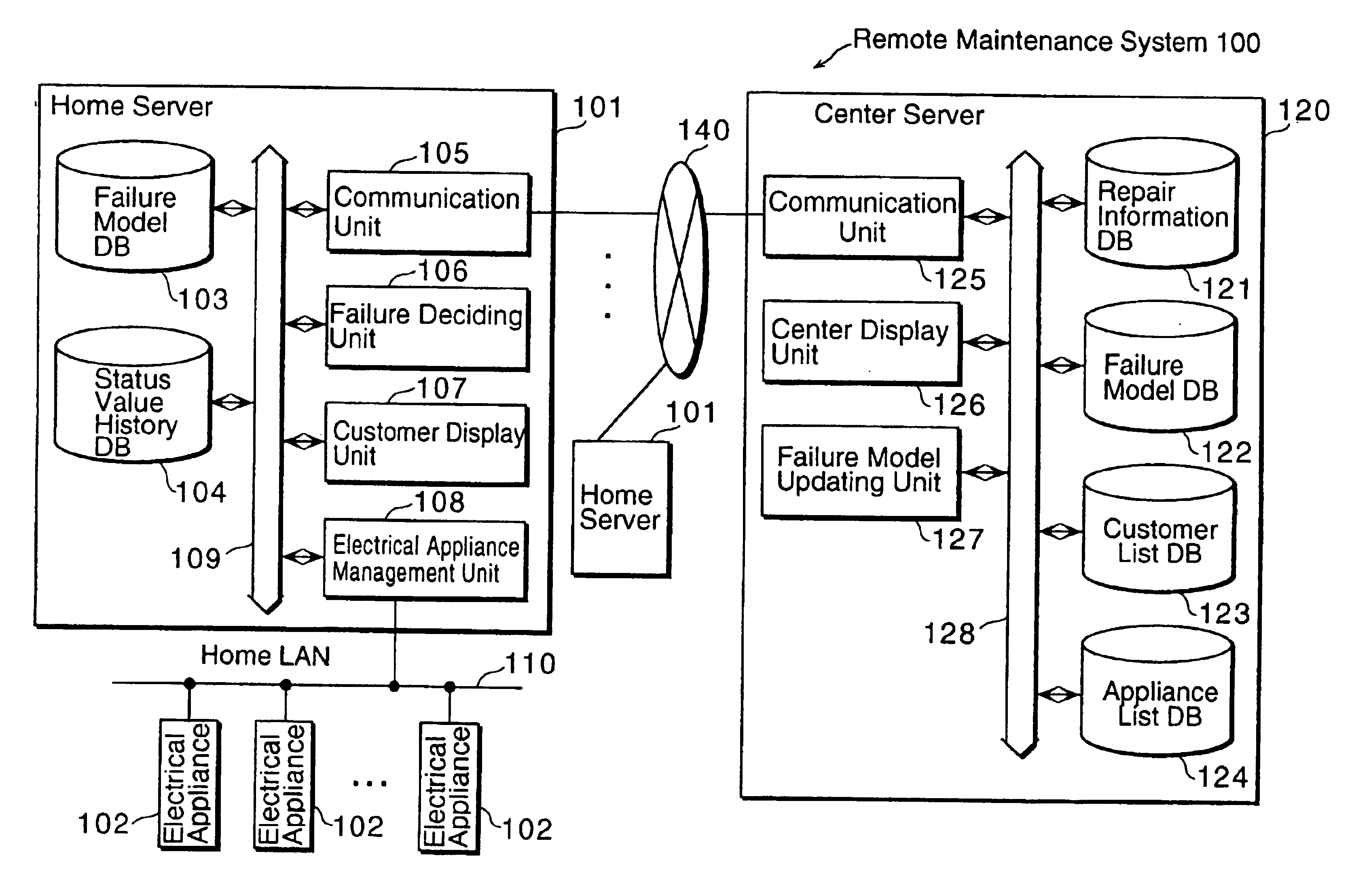
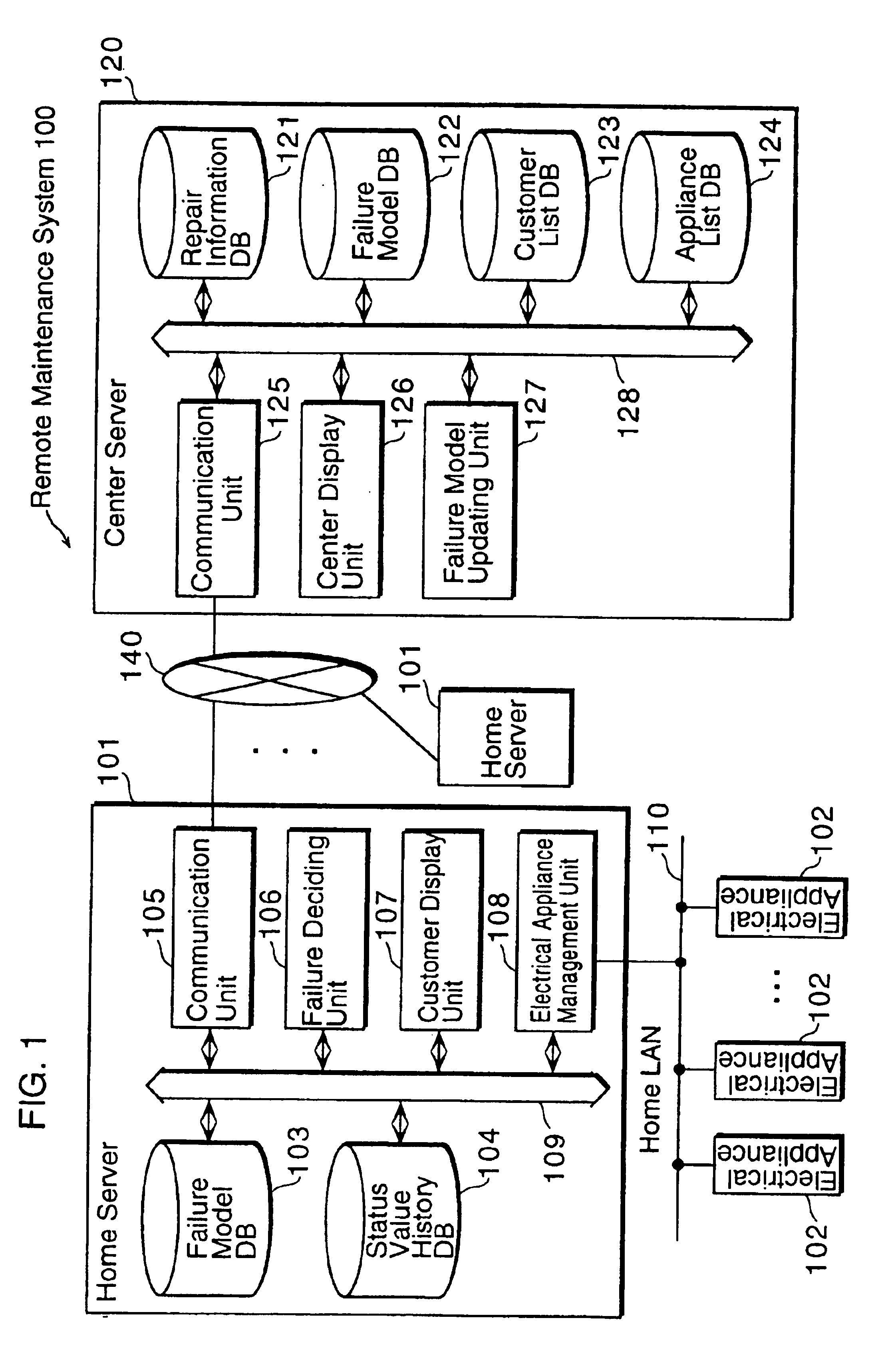
The following is an explanation of the embodiment for the present invention with reference to FIGS. 1.about.11B. FIG. 1 is a block diagram showing a configuration of a remote maintenance system 100 of the present embodiment. The remote maintenance system 100 is a system in which a home server in a house diagnoses a failure of an electrical appliance located in each house based on a failure model, displays repair information for the failure to a user, stores status values of the appliance up to the time of the failure occurrence, and sends them to a center server, and the center server displays details of repair for the failure to a serviceman, updates a failure model based on the status values in normal operation, and sends the updated failure model to the home server. The remote maintenance system 100 includes a plurality of home servers 101 and a center server 120. Each of the home servers 101 is connected to the center server 120 respectively via a communication network 140.

The ...


PUM


Abstract

A remote maintenance system has a center server that is located in a service center for performing maintenance of an electrical appliance and a home server that is located in a house and monitors a status of the electrical appliance 102 in the house which are connected via a communication network. The home server includes an electrical appliance management unit that acquires a status value of the electrical appliance, a communication unit that receives from the center server a failure model which is information defining a method of deriving a decision whether the electrical appliance has failed or not from the status value, and a failure deciding unit that decides whether the electrical appliance has failed or not based on the acquired status value and the received failure model using qualitative reasoning. The center server includes a failure model updating unit that updates a failure model and sends the updated failure model to the home server via a communication unit.

Description

(1) Field of the InventionThe present invention relates to a remote maintenance system that makes an automatic failure diagnosis of electrical appliances for family use using a communication line, and transmits failure information to a service management center.(2) Description of the Prior ArtA conventional remote maintenance system that detects malfunction of an electrical appliance located in each house quickly and correctly, and automatically reports it to a service center which provides maintenance services of the electrical appliance has been developed. In this type of remote maintenance system, a home server is located in each house under a maintenance contract of the electrical appliance with the service center, and the home server is connected to a center server which is located in the service center via a communication network. Each electrical appliance includes a monitor circuit for monitoring an internal state of itself, and reports the monitored internal state to the hom...

Claims


Application Information

Patent Timeline
Patent Type & Authority Patents(United States)
IPC IPC(8): G05B23/02H04L12/28G06F11/273G06F13/00G06Q10/00G06Q50/00G06Q50/10H04L12/24H04M11/00H04Q9/00
CPCG05B23/0245G05B23/0297G06F11/2294H04L12/24H04L12/2803H04L12/2825H04L41/00H04L41/0677G05B2219/25168H04L2012/2845H04L2012/2849H04L2012/285H04M11/00
Inventor MURAKAMI, TAKASHISHINTANI, YASUYUKINAGAMITSU, SACHIO
Owner PANASONIC CORP
Why Eureka
Try Eureka