
Scalable switch fabric system and apparatus for computer networks

a switch fabric and computer network technology, applied in the direction of electrical equipment, digital transmission, data switching by path configuration, etc., can solve the problems of inability to implement fc sans, limited expansion of sans, and inability to meet the needs of most wide area networks ("wans") or metropolitan area network configurations

Inactive Publication Date: 2003-10-30
MAXXAN SYST
View PDF4 Cites 126 Cited by
  • Summary
  • Abstract
  • Description
  • Claims
  • Application Information

AI Technical Summary

Benefits of technology

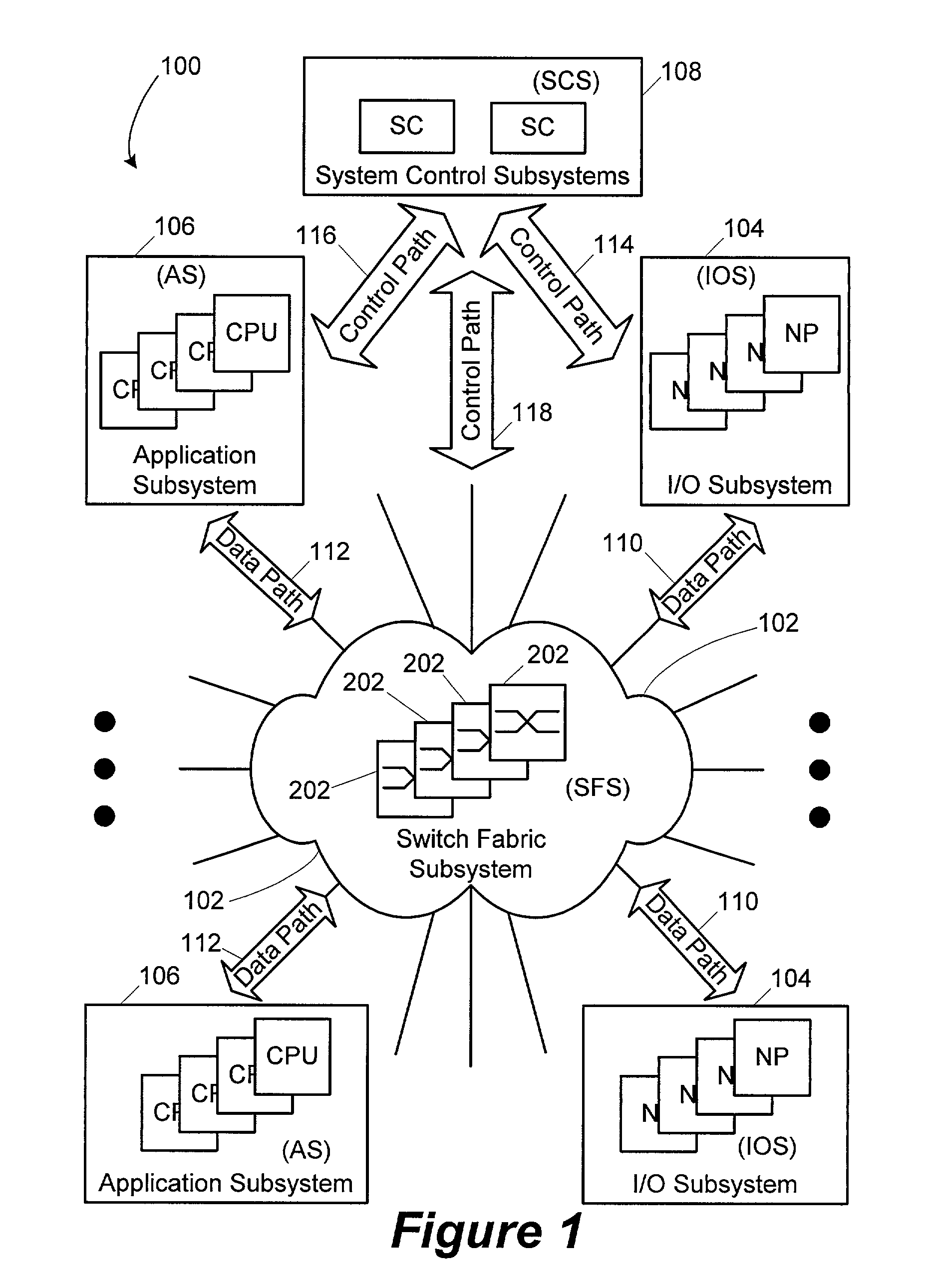
[0089] The Application or General Purpose Processor(s) 710 execute software that provides the high level services needed in the storage network switch. These processors are preferably off-the-shelf high-performance CISC or RISC processors such as those used in servers and workstations. Preferably the AS 106 partitions the frame level processing from the high level service software in the system. Frames received on the external ports of the IOS 104 are parsed, and a determination is decided at the low level protocol layers whether or not to forward the frame to an appropriate AS 106. A good deal of the information that is parsed in the frame can be inserted into the frames so that once they are forwarded to the AS 106, the application processors can skip the low level processing and immediately process the high level protocols, thus drastically improving performance relative to application appliances or servers that are external to a switch. An advantage of the present invention is that the application appliance may be directly integrated into the storage network switch which results in tight functional coupling with the NPs in the IOS 104.
[0090] The AP(s) 710, ANB 712, HSBs 715, HSB / PCI Bridge 716, I / O busses 714, and I / O controllers (FC and Gigabit Ethernet) 718 may be used to develop the AS 106 in a manner that allows high performance through tight integration of the low level protocol processing done in the IOS 104 with the high level processing done by the AS 106 specific components. The AS 106 specific components may provide the same functionality as an external appliance, workstation, or server. The AP(s) 710 may execute on a variety of operating systems including Linux, embedded Windows, manufactured by the Microsoft Corporation of Redmond, Wash., and off-the-shelf real-time operating systems like Wind River's VxWorks and the like. System Control Subsystem ("SCS")
[0091] The SCS 108 (see FIG. 1) provides the overall system management for the storage network switch 100. System management comprises: 1) providing the physical and logical interface for the user to manage and control the storage network switch; and 2) providing the central focal point for control information in the switch for the proper operation of all protocols and functionality provided by the storage network switch. Providing the management interface to the storage network switch means that, via either the local Ethernet and / or the serial ports, a user can manage the switch using management application tools (e.g., network management applications like HP Openview, manufactured by the Hewlett-Packard Corporation of Palo Alto, Calif.; BMC Patrol, manufactured by BMC Software of Houston, Tex., etc.) or standard communications tools like TELNET terminals, SSH terminals, serial attached console terminals (VT 100) or terminal emulation programs (e.g., Microsoft Windows Hyperterminal). The SCS 108 implements the standard SNMP with management information bases ("MIBs") and protocols to allow it to be managed remotely from custom or industry standard management applications. Likewise, the SCS 108 implements a command line interface ("CLI") that can be accessed directly via a physical serial port or remotely via TELNET over TCP / IP over the Ethernet.
[0092] The SCS 108 may be implemented using a pair of System Control Cards ("SCC") 900 that operate in an active / standby pair. FIG. 9 illustrates the overall architecture of the major components on each SCC 900. On power up, the two SCCs initialize themselves and then negotiate for the active status. This negotiation process takes place via the use of the Redundancy Control Logic ("RCL") 918 which manipulates a set of redundancy control signals 924 that are connected between the two SCCs 900. The RCL 918 and the redundancy control signals 924 implement an arbiter function that allows only one of the SCCs to be active at one time. Once the controllers decide which SCC 900 may be active, the other SCC 900 may assume the standby role. The active SCC 900 may have all tasks, processes, and interfaces active for operating the switch and interfacing to the users / administrators of the switch. The standby SCC 900 may place most of its tasks, processes and interface in a quiescent state. Preferably, the only software function actively executed on the standby SCC controller 900 is a redundancy component that copies changes to the configuration of the switch, error logs and other control data structures from the active SCC 900 needed in case the standby SCC 900 must become the active card.
[0093] A feature of the present invention is that in the event of a software or hardware failure on the active SCC 900, the software / hardware may initiate a fail-over event in the fault tolerant logic of the standby SCC 900, such that the active SCC 900 immediately releases active control and the standby SCC 900 immediately assumes the active status. In this event, the software in the newly controlling SCC 900 may activate all its tasks, processes and interfaces in order to begin processing management requests and to continue the operational control of the switch system.System Control Processor ("SCP")
[0094] The System Control Processor ("SCP") 910 may be an off-the-shelf general purpose microprocessor that provides enough CPU computing power and data throughput to perform the system management and operation control of the storage network switch 100 of the present invention.Embedded Memory Controller and I / O Bus Bridge ("North Bridge")

Problems solved by technology

Expansion of SANs is limited in that conventional FC SANs cannot be implemented over geographically distant locations.
Conventional FC architecture is not suitable for most wide area networks ("WANs") or metropolitan area network configurations.
While TCP / IP and Ethernet may be used to implement block storage protocols over a WAN / LAN, these two protocols are not efficient for block storage applications.
Interconnecting heterogeneous SANs that may be easily scaled upward using these translation bridges is very difficult because the translation bridges usually become the bottleneck in speed of data transfer when the clients (servers and / or storage devices) become larger in number.
In addition, in a mixed protocol environment and when the number of different protocols increase, the complexity of the software installed on the translation bridges increases, which further impacts performance.
Other limitations of the size of SANs, in terms of storage capacity, are cost and manpower.
Another major, if not primary, expense is the cost of managing a SAN.
SAN management requires a great deal of manpower for maintenance and planning.
For example, as storage capacity grows, issues such as determining server access to storage devices, backup strategy, data replication, data recovery, and other considerations become more complex.

Method used


Image

  • Scalable switch fabric system and apparatus for computer networks
  • Scalable switch fabric system and apparatus for computer networks
  • Scalable switch fabric system and apparatus for computer networks

Examples


example 1

OVERVIEW OF EXAMPLE 1

[0145] The basic system of the present invention is illustrated in FIG. 16a. The system 1600 is composed of, for example, a host 1602, two line cards 1604 and 1608, a system card 1606, and a storage device 1610. In this illustrative example, the host 1602 may send a write statement that is to be performed (ultimately) by the storage device 1610. However, it will be clear to those skilled in the art that a wide variety of other READ or WRITE scenarios may be envisioned where the host 1602 and / or the storage device 1610 are replaced with other devices that have similar or alternate functionality in conjunction with the storage network switch of the present invention.

[0146] According to this illustrative example, the host 1602 is coupled to the first line card 1604. The first line card 1604 itself is coupled to the system card 1606 and the second line card 1608, as illustrated in FIG. 16a. Finally, the second line card 1608 is coupled to the system card 1606 and to...

example 2

OVERVIEW OF EXAMPLE 2

[0152] Another example embodiment of the basic system of the present invention is illustrated in FIG. 16b. The system 1600 is composed of, for example, a host 1602, three line cards 1604, 1608 and 1614, a system card 1606, an application blade 1616, one or more switch fabric card(s) 1612, and a storage device 1610. In this illustrative example, the host 1602 may send a write statement that is to be performed (ultimately) by the storage device 1610. However, it will be clear to those skilled in the art that a wide variety of other READ or WRITE scenarios may be envisioned where the host 1602 and / or the storage device 1610 are replaced with other devices that have similar or alternate functionality in conjunction with the storage network switch of the present invention.

[0153] According to this illustrative example of FIG. 16b, the host 1602 is coupled to the first line card 1604. The storage device 1610 is coupled to the second line card 1608. The application blad...


PUM


Abstract

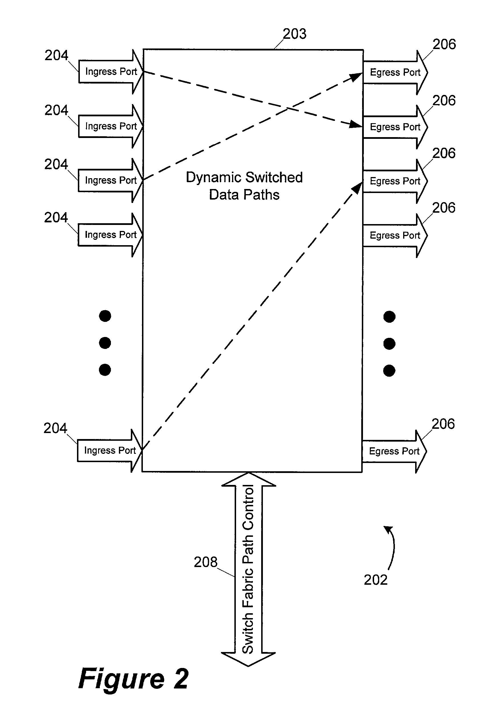
A scalable switch fabric system and apparatus for computer networks. The scalable switch fabric system and apparatus comprises a Switch Fabric Subsystem, Input-Output Subsystems, Application Subsystems and System Control Subsystems. The Switch Fabric Subsystem is a protocol agnostic cell or packet switching infrastructure that provides scalable interconnections between the Input-Output Subsystems and Application Subsystems. The Switch Fabric Subsystem provides primary data paths for network traffic being moved by the switch. The Input-Output Subsystems connect to the external network devices that use the switch to communicate with other external network devices. The Input-Output Subsystems are part of the data path and do low level decoding of ingress frames from the external ports; switching / routing, identifying the destination Input-Output Subsystems for the frame; and queuing the frame for transmission through the Switch Fabric. The System Control Subsystems provide overall management of the scalable switch fabric system and apparatus.

Description

[0001] This application is related to U.S. patent application Ser. No. ______ [attorney docket number 069099.0104 / client reference 106-02] entitled "System and Method for Scalable Switch Fabric for Computer Network" by [name inventors], which is being filed contemporaneously with the present application and which is incorporated herein by reference in its entirety for all purposes. This application is also related to previously filed and pending U.S. patent application Ser. No. 09 / 738,960, entitled "Caching System and Method for a Network Storage System" by Lin-Sheng Chiou, Mike Witkowski, Hawkins Yao, Cheh-Suei Yang, and Sompong Paul Olarig, which was filed on Dec. 14, 2000 and which is incorporated herein by reference in its entirety for all purposes; U.S. patent application Ser. No. 10 / 015,047 [attorney docket number 069099.0102 / B2] entitled "System, Apparatus and Method for Address Forwarding for a Computer Network" by Hawkins Yao, Cheh-Suei Yang, Richard Gunlock, Michael L. Wit...

Claims


Application Information

Patent Timeline
IPC IPC(8): H04L12/24H04L12/56
CPCH04L12/5601H04L41/0213H04L2012/5665H04L49/255H04L49/3081H04L41/20
Inventor WITKOWSKI, MICHAELCHIOU, LIH-SHENGOLARIG, SOMPONG PAULJENNE, JOHN E.REYES, MILES BORROMEO
Owner MAXXAN SYST
Learn More