
Data transfer method and system for loudspeakers in a digital sound reproduction system

a digital sound reproduction system and loudspeaker technology, applied in the field of data transfer methods, can solve the problems of random latency in travel time and random latency that cannot be predicted

Active Publication Date: 2015-01-06
GENELEC
View PDF23 Cites 146 Cited by
  • Summary
  • Abstract
  • Description
  • Claims
  • Application Information

AI Technical Summary

Benefits of technology

[0008]The invention is based on implementing network packet time stamping in network protocol stack so that accurate time for send and receipt of packets can be determined. In a preferred embodiment the receiver software implements the time stamping directly in the Ethernet driver (for which we have source code) for the most accurate operation possible.

Problems solved by technology

Basically the quality of the reproduction in these systems is very good for home use but for professional use the digital transfer technology causes some problems.
This is difficult for two reasons.
First, standard network socket API will introduce random latency between calling the user-mode send-function and the actual output of the packet depending on the status of the operating system.
Secondly, when packet travels through network it will go through one or more hubs, switches or routers.
This introduces random latency in travel time that cannot be predicted.

Method used


Image

  • Data transfer method and system for loudspeakers in a digital sound reproduction system
  • Data transfer method and system for loudspeakers in a digital sound reproduction system
  • Data transfer method and system for loudspeakers in a digital sound reproduction system

Examples


Embodiment Construction

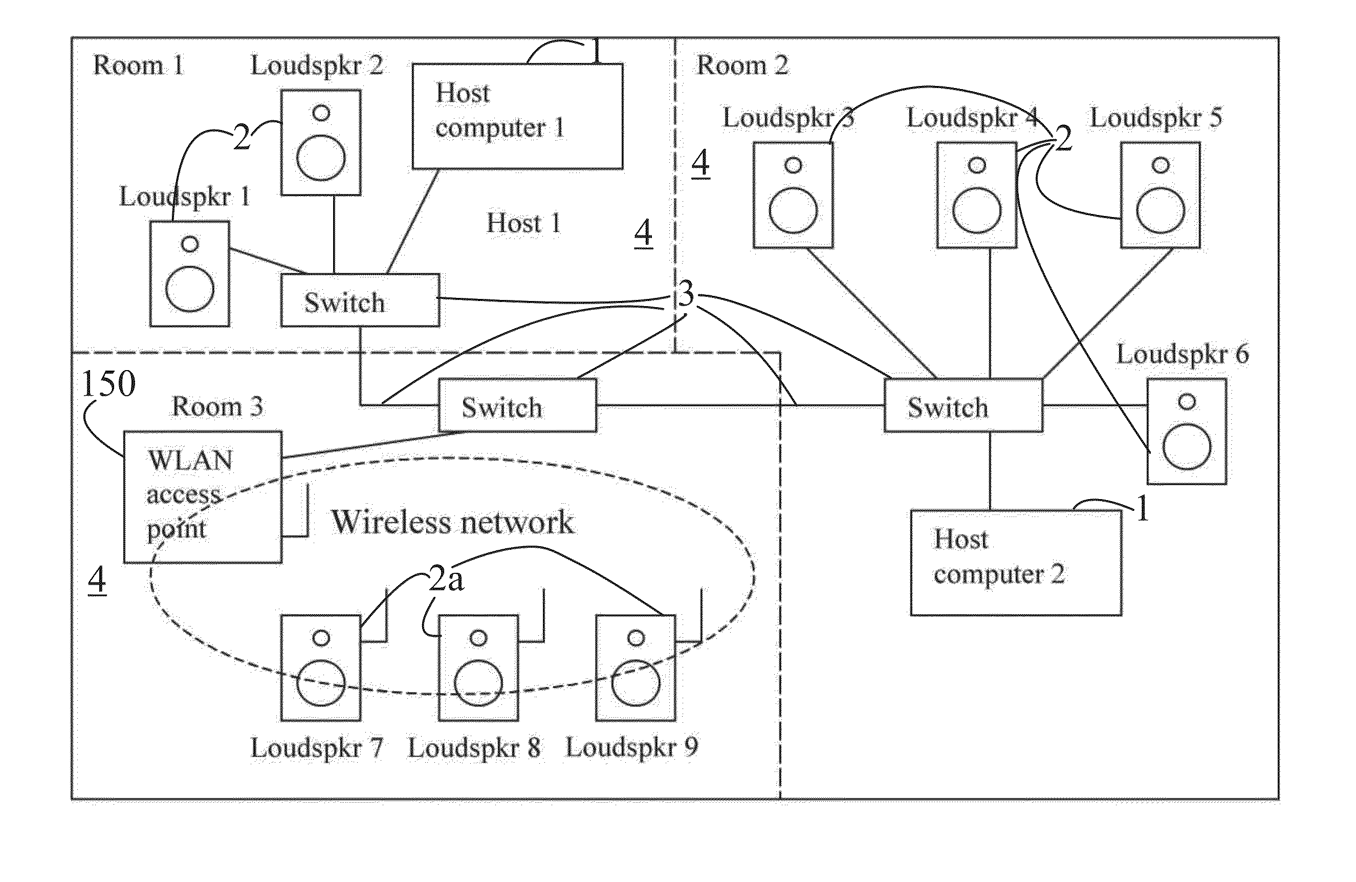
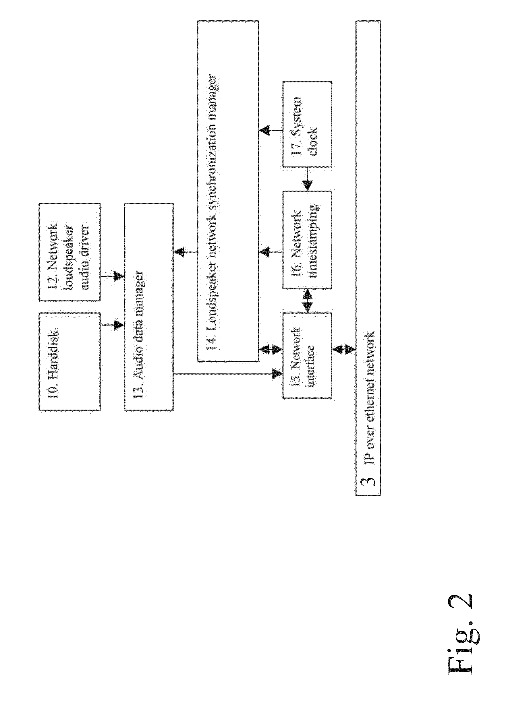
[0024]In the invention, the following terminology is used in connection with the reference numbers. However, the list is not exhaustive especially relating to the block and flow diagrams of FIGS. 7-11:[0025]1 host or host data source[0026]2 receiver, digital loudspeaker,[0027]2a wireless receiver[0028]3 switch, network[0029]4 group of receivers[0030]10 hard disc[0031]12 virtual software audio adapter (driver)[0032]13 audio data manager[0033]14 synchronization manager[0034]15 network interface[0035]16 network timestamping[0036]17 system clock[0037]20 network interface[0038]22 timer hardware[0039]23 adjustable oscillator[0040]24 loudspeaker networks communications[0041]25 synchronization controller[0042]26 digital to analog conversion[0043]27 audio stream controller[0044]28 data output controller[0045]29 sample rate converter[0046]60 synchronization signal / ECHO REQ[0047]61 Return message / ECHO RESP[0048]62 Control Command / SET CLOCK[0049]150 Wireless Local Area Network (WLAN) access poi...


PUM


Abstract

The present publication describes a data transfer method and system in a digital sound reproduction system. The method comprises method steps for generating a digital audio stream for multiple channels in a host data source, e.g. a computer, the audio stream is formed by multiple consecutive samples, receiving the digital audio stream sent by the host data source through a digital data transmission network by several digital receivers each of which including a microcontroller with a clock, the receivers further including means for generating an audio signal. In accordance with the invention the host data source sends repeatedly a synchronization sample to at least one receiver, the receiver replies to the synchronization sample by a return sample, the host calculates a latency (T) for each receiver based on the sending time (Th1) of the synchronization sample and the reception time (Th2) of the return sample and the processing time (Tt1-Tt2) of the receiver, the host sends to the receiver information of the calculated latency (T) in combination with the time stamp the measurement time, based on this information the receiver adjusts the function of its clock, and the above synchronization steps are repeated continuously.

Description

FIELD OF INVENTION[0001]The present invention relates to a data transfer method according to the preamble of Claim 1.[0002]The invention also relates to a data transfer system.BACKGROUND OF INVENTION[0003]According to the prior art, there are several commercial system for digital audio reproduction in digital networks. For example following products are available today. The Gibson MaGIC™ network Cobra Net™, EtherSound™, Livewire™, MADI™ and others describe systems by which audio data may be streamed to digital loudspeakers or sound reproduction systems. Basically the quality of the reproduction in these systems is very good for home use but for professional use the digital transfer technology causes some problems.[0004]In accordance with the prior art the above problem has been solved by buffering the information into receivers and controlling the unloading of the information from the receivers.[0005]In more detail, to synchronize clocks over Ethernet connections the exact travel ti...

Claims


Application Information

Patent Timeline
Patent Type & Authority Patents(United States)
IPC IPC(8): G06F17/00H04J3/06H04L49/9023H04R3/12H04R27/00
CPCH04R3/12H04J3/0667H04R27/00H04R2227/003H04R2227/005
Inventor HAATAINEN, NIKO
Owner GENELEC
Learn More