Clamping mechanism for device for testing high-temperature direct tensile strength of ultrahigh-temperature ceramics

A technology of ultra-high temperature ceramics and tensile strength, which is used in measuring devices, using stable tension/pressure to test the strength and strength characteristics of materials, etc. Achieve the effect of avoiding bending and twisting, accurate test results, and uniform force

Inactive Publication Date: 2015-02-04
CHONGQING UNIV
View PDF10 Cites 25 Cited by
  • Summary
  • Abstract
  • Description
  • Claims
  • Application Information

AI Technical Summary

Problems solved by technology

Its shortcoming is that due to the deviation of the alignment of the upper and lower hemispherical gyroscopes, the center line of the installed material cannot completely coincide with the tension line, and it cannot adapt to the clamping test in the high temperature test.
[0004] Since the test of the high temperature tensile strength of ultra-high temperature ceramics is carried out in a high temperature test chamber, on the one hand, due to the space limitation of the high temperature test chamber, the clamping mechanism requires small size, reliable clamping, high temperature resistance, etc.; During the test, due to the high brittleness of the ultra-high temperature ceramic material, a slight uneven force on the specimen may cause damage to the specimen, and accurate test results cannot be obtained. Therefore, ensure that the centerline of the specimen and the direction of the force are located at The technical difficulty on the same straight line is greater than that in the normal temperature environment

Method used


Image

  • Clamping mechanism for device for testing high-temperature direct tensile strength of ultrahigh-temperature ceramics
  • Clamping mechanism for device for testing high-temperature direct tensile strength of ultrahigh-temperature ceramics
  • Clamping mechanism for device for testing high-temperature direct tensile strength of ultrahigh-temperature ceramics

Examples


Embodiment Construction

[0018] Below in conjunction with accompanying drawing and embodiment the present invention will be further described:

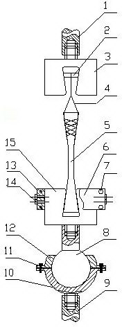
[0019] Such as figure 1 As shown, the present invention includes an upper clamping part and a lower clamping part, and the upper clamping part includes an upper wedge-shaped clamp 3, a circular support beam 2 and a cable 4, and the upper wedge-shaped clamp 3 is connected with the upper pull rod 1 of the testing machine, The circular support beam 2 is horizontally clamped in the wedge-shaped groove of the upper wedge-shaped fixture 3, and the flexible cable 4 used to wind and fix the upper end of the test piece 5 is wound together with the circular support beam 2 and fixed; the lower clamping part includes a lower wedge-shaped Fixture 15, ball stud 8, lower spherical bearing 10 and upper spherical bearing 12, the lower wedge-shaped clamp 15 for clamping the lower end of test piece 5 is connected with ball stud 8, and the ball head of ball stud 8 is installed o...


PUM


Abstract

The invention discloses a clamping mechanism for a device for testing the high-temperature direct tensile strength of ultrahigh-temperature ceramics. The clamping mechanism is structurally characterized in that an upper wedge clamp (3) is connected with an upper pull rod (1) of a tester, a circular supporting beam (2) is transversely clamped in a wedge groove of the upper wedge clamp (3), a flexible cable (4) for fixing a test piece (5) by being wound around the upper end of the test piece (5) is wound and fixed together with the circular supporting beam (2), a lower wedge clamp (15) for clamping the lower end of the test piece (5) is connected with a bulb rod (8), a bulb of the bulb rod (8) is mounted in a ball bowl composed of an upper spherical bearing (12) and a lower spherical bearing (10), and the upper spherical bearing (12) and the lower spherical bearing (10) are connected with each other by use of a bolt (11). The clamping mechanism for the device for testing the high-temperature direct tensile strength of the ultrahigh-temperature ceramics has the beneficial effects that the center line of the test piece is located in the same straight line with the straight line of pull under the action of the pull, the test piece is prevented from being bent and distorted, the stress on the test piece in the center line is even, a test result is kept accurate and reliable, and the repeatability is good.

Description

technical field [0001] The invention relates to a device for testing the tensile strength of solid materials, in particular to a clamping mechanism for the device for testing the direct tensile strength of ultra-high temperature ceramics at high temperature. Background technique [0002] Ultra-high temperature ceramics (UHTCS for short) refers to the most heat-resistant high-grade ceramics that can still be used as usual under the conditions of over 2000°C and oxygen. It is mainly used in thermal protection systems of aircraft such as hypersonic missiles and space shuttles, such as wing leading edges, end caps and hot ends of engines. The high-temperature direct tensile strength mentioned in this patent application refers to the direct tensile strength at a temperature ranging from 200°C to 2000°C. [0003] Chinese patent document CN 103954496 A disclosed on July 30, 2014 "a high-degree-of-freedom brittle material straight-pull test device and its test method", which includ...

Claims


Application Information

Patent Timeline
Patent Type & Authority Applications(China)
IPC IPC(8): G01N3/18G01N3/02G01N3/04
Inventor 李卫国成天宝麻建坐李定玉王如转寇海波方岱宁
Owner CHONGQING UNIV
Why Eureka
Try Eureka