Rotatable camera that moves a camera lens unit in a panning or tilting motion by a single motor

a technology of rotating camera and lens unit, which is applied in the field of rotating cameras, can solve the problems of deficiency of monitoring, inability of the lens unit to reach the desired direction quickly and precisely, and neglected monitoring of corners

Inactive Publication Date: 2010-05-18
COMPAL ELECTRONICS INC
View PDF7 Cites 23 Cited by
  • Summary
  • Abstract
  • Description
  • Claims
  • Application Information

AI Technical Summary

Benefits of technology

[0007]Owing to the above, the major purpose of the present invention is to provide a camera with rotatable lens which employs only a single motor to drive the camera lens and move the lens rapidly to the direction to be monitored, and therefore will not cause any corner neglected to be monitored due to time delay.
[0009]The camera of the invention also has a suspended cushion mechanism to provide cushion effect between the photographing head and the driving rod, when the driving rod moves in circular manner following a spiral shaped locus originated by the spiral shaped rail on the curved guiding pan of the rotatable disc, the suspended cushion mechanism can enable a smooth rotating motion of the photographing head of the lens unit inside the spherical bearing support.

Problems solved by technology

However, this type of ball shaped camera has the drawback that the panning and tilting of camera lens driven by two motors separately always causes the lens unable to reach the desired direction rapidly and precisely.
During scanning for monitoring, time delay is always resulted in the ball shaped camera unable to move the lens in time to the direction to be monitored that causes deficiency of monitoring and some corners neglected to be monitored.

Method used


Image

  • Rotatable camera that moves a camera lens unit in a panning or tilting motion by a single motor
  • Rotatable camera that moves a camera lens unit in a panning or tilting motion by a single motor
  • Rotatable camera that moves a camera lens unit in a panning or tilting motion by a single motor

Examples


Embodiment Construction

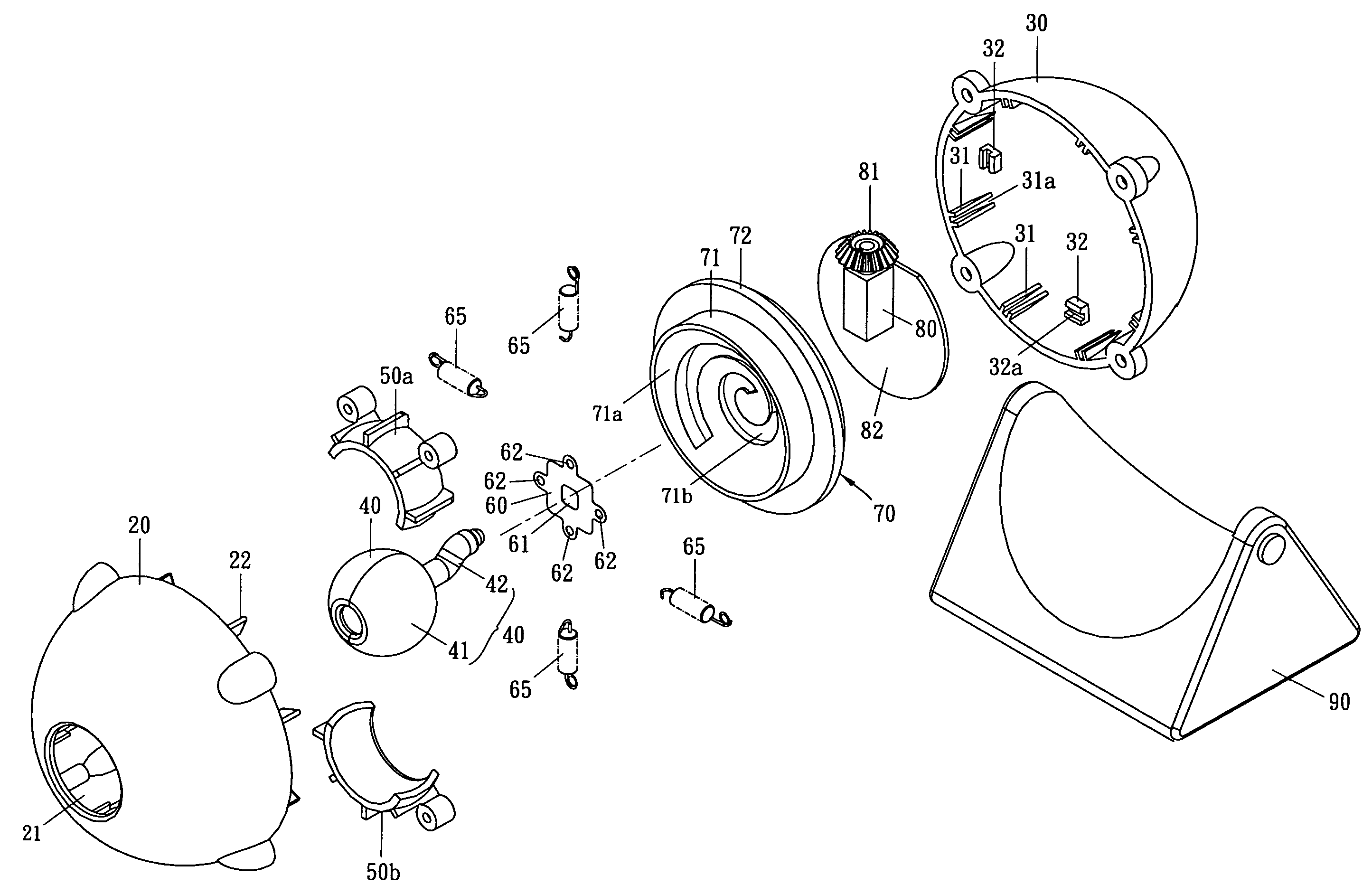
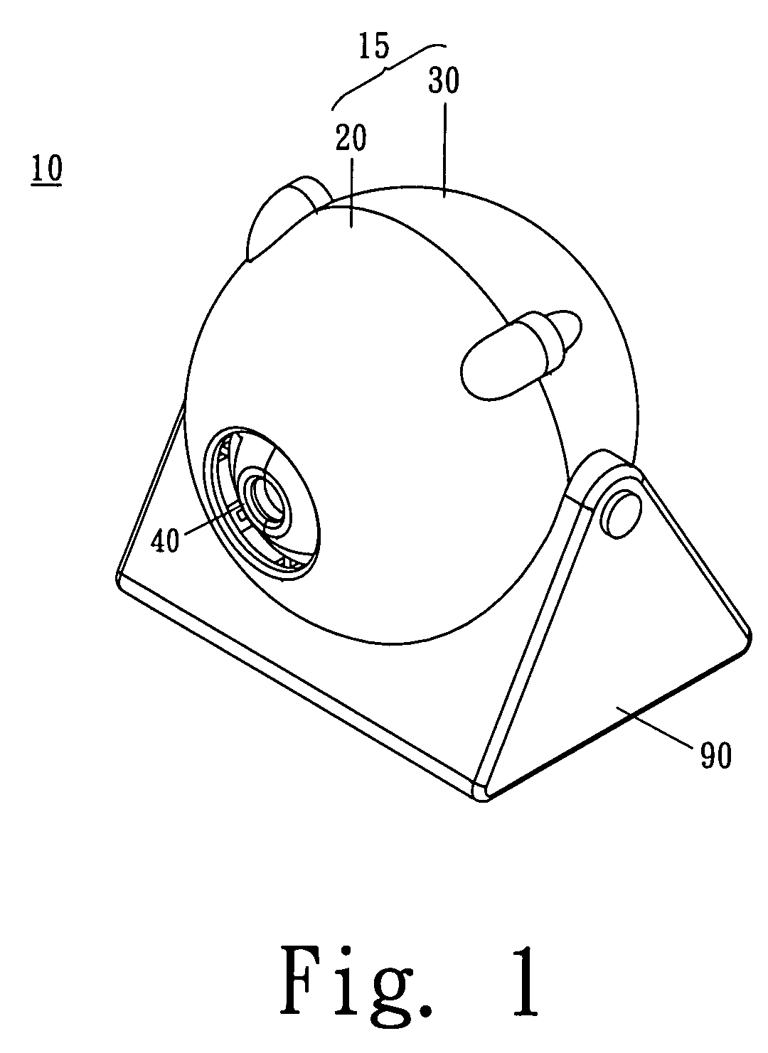
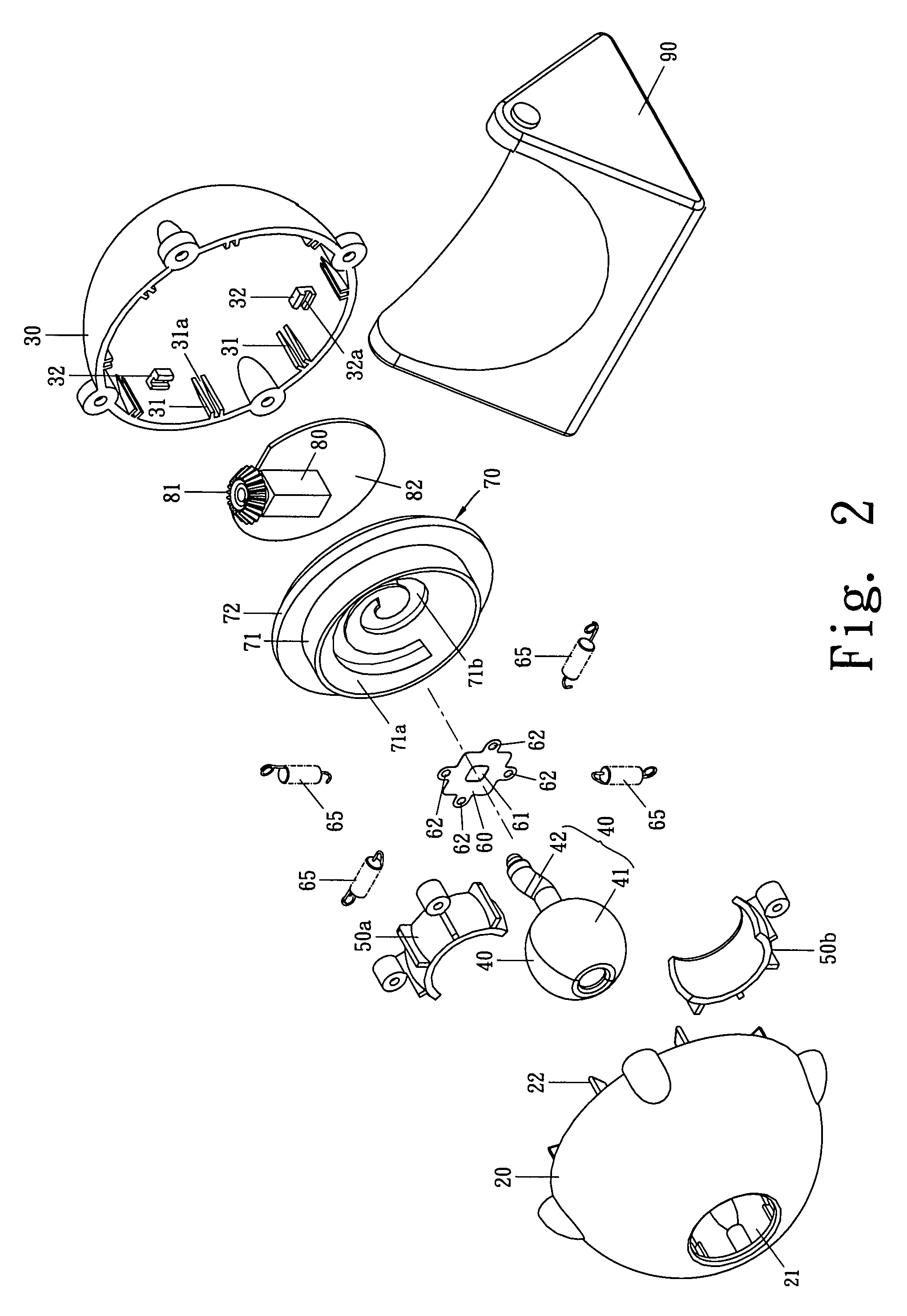
[0014]As illustrated in from FIG. 1 to FIG. 4, a rotatable camera 10 of the invention comprises a housing 15, a base seat 90 and a lens unit 40 pivotally installed inside the housing 15, wherein the housing 15 comprises a front case 20 and a rear case 30, and in addition to the lens unit 40 the housing 15 also has a spherical bearing support 50, a suspended cushion mechanism 60, a rotatable disc 70 and a motor 80. When the motor 80 is running, the rotatable disc 70 is driven by the motor 80 to rotate which in turn drive the lens unit 40 to generate rotating and swinging motion.

[0015]The front case 20 is a half sphere shaped part having an opening 21, plural fixing fins 22, plural fixing studs 23 and rib case-portions 24 inside, wherein the fixing fins 22 are for engaging and connecting to the fixing slots 31a of rear case 30 and for enabling the rotating pan 70 to make a pivotal connection inside the rear case 30. The fixing studs 23 are for mounting one end of the spring element 65...


PUM


Abstract

A rotatable camera has a motor, a lens unit comprising a photographing head and a driving rod coupled to the photographing head, a spherical bearing support for pivotally mounting the photographing head, and a rotatable disc driven in rotation motion by the motor to drive the driving rod of the lens unit move along a spiral shaped locus, and, when the motor is driven, the photographing head is at the same time driven by the driving rod to rotate and change its angular position, so that the rotatable camera employs only a single motor to drive the photographing head of the lens unit to rapidly move to the direction to be monitored, particularly, due to no time delay any corners shall be monitored by the rotatable camera.

Description

BACKGROUND OF THE INVENTION[0001]1. Field of the Invention[0002]The invention relates to a rotatable camera, particularly to a ball shaped camera equipped with only one motor for varying the angle of camera lens.[0003]2. Description of the Related Art[0004]In the current technology for designing a known ball shaped camera, two driving motors are commonly employed to make the camera lens able to move universally 360 degree. In the motorized mechanism of the ball shaped camera, one of the motors is for controlling the panning of the camera lens in horizontal direction while the other motor is for controlling the tilting of the camera lens in vertical direction so that the camera lens can move both in panning and tilting manner.[0005]However, this type of ball shaped camera has the drawback that the panning and tilting of camera lens driven by two motors separately always causes the lens unable to reach the desired direction rapidly and precisely.[0006]During scanning for monitoring, t...

Claims


Application Information

Patent Timeline
Patent Type & Authority Patents(United States)
IPC IPC(8): H04N5/225
CPCH04N5/23238H04N5/2252H04N23/51H04N23/698
Inventor KUNG, SHAO-TSULIN, PO-ANCHEN, YUNG-HUI
Owner COMPAL ELECTRONICS INC
Why Eureka
Try Eureka