Fluid heater

a technology of fluid heater and heater body, which is applied in the field of heaters, can solve the problems of circuitry increasing the cost of manufacturing fluid heaters, the need to control the on/off duty cycle of electric heater elements, and the creation of maintenance and reliability concerns

Inactive Publication Date: 2005-10-18
ALGAS SDI INT
View PDF51 Cites 34 Cited by
  • Summary
  • Abstract
  • Description
  • Claims
  • Application Information

AI Technical Summary

Benefits of technology

[0010]According to one embodiment of the present invention, a fluid heater is provided, including a first heat exchanger block, a fluid heating tube configured to receive a fluid to be heated, and a second heat exchanger block having a second fluid heating tube configured to receive a fluid to be heated. The first block and the second block have their internal surfaces facing each other.

Problems solved by technology

A problem with such known fluid heaters is the need to control the on/off duty cycle of the electric heater elements to prevent overheating.
The circuitry required creates safety concerns and, in addition, maintenance and reliability concerns are created.
Further, the circuitry increases the cost of manufacturing the fluid heaters.
Another p

Method used


Image

  • Fluid heater
  • Fluid heater
  • Fluid heater

Examples


Embodiment Construction

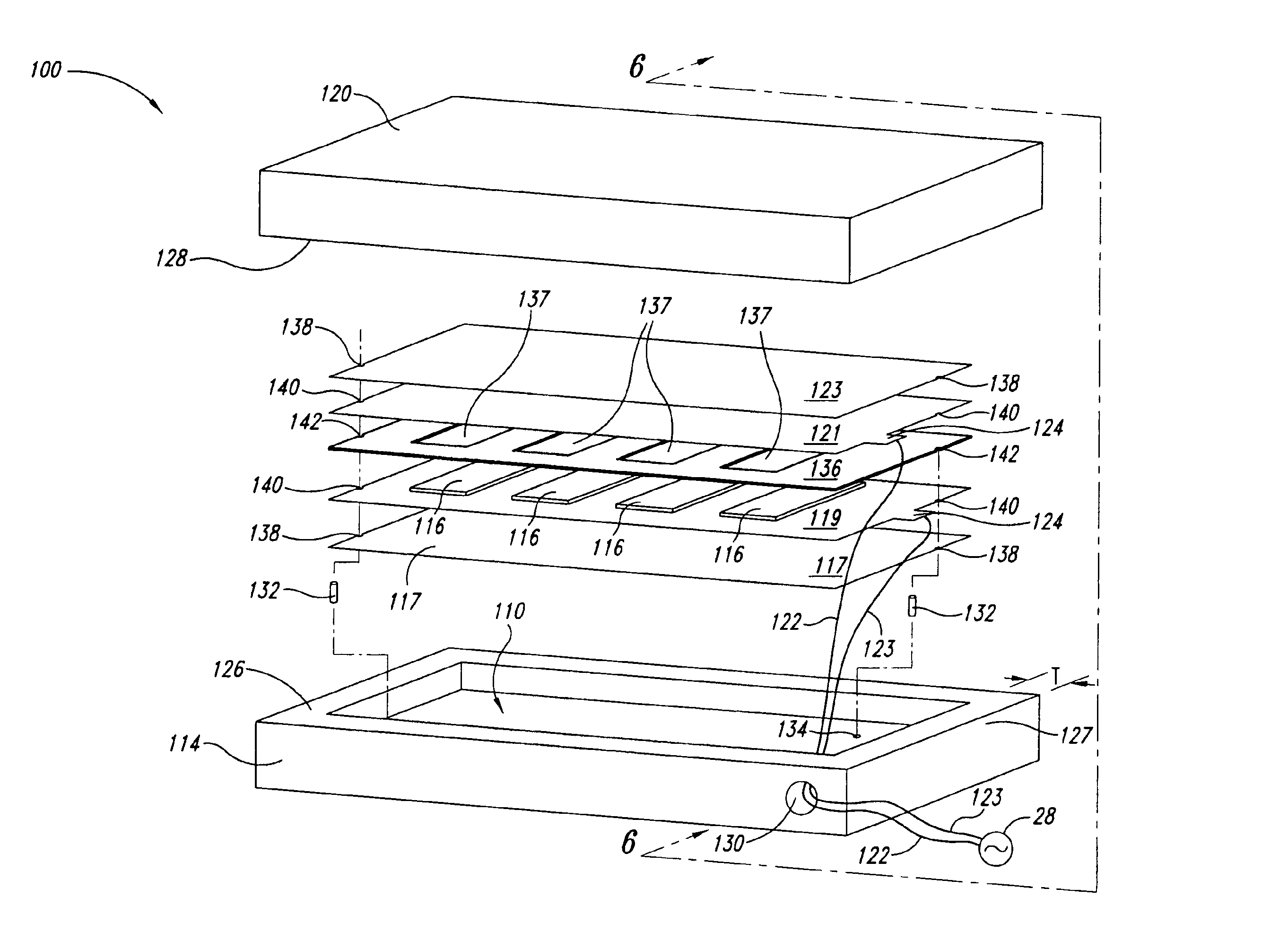
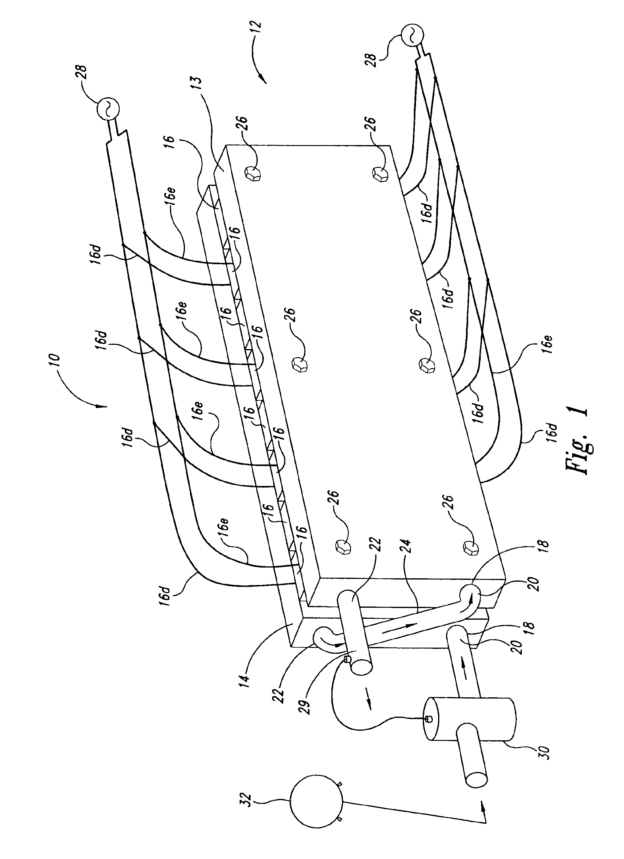
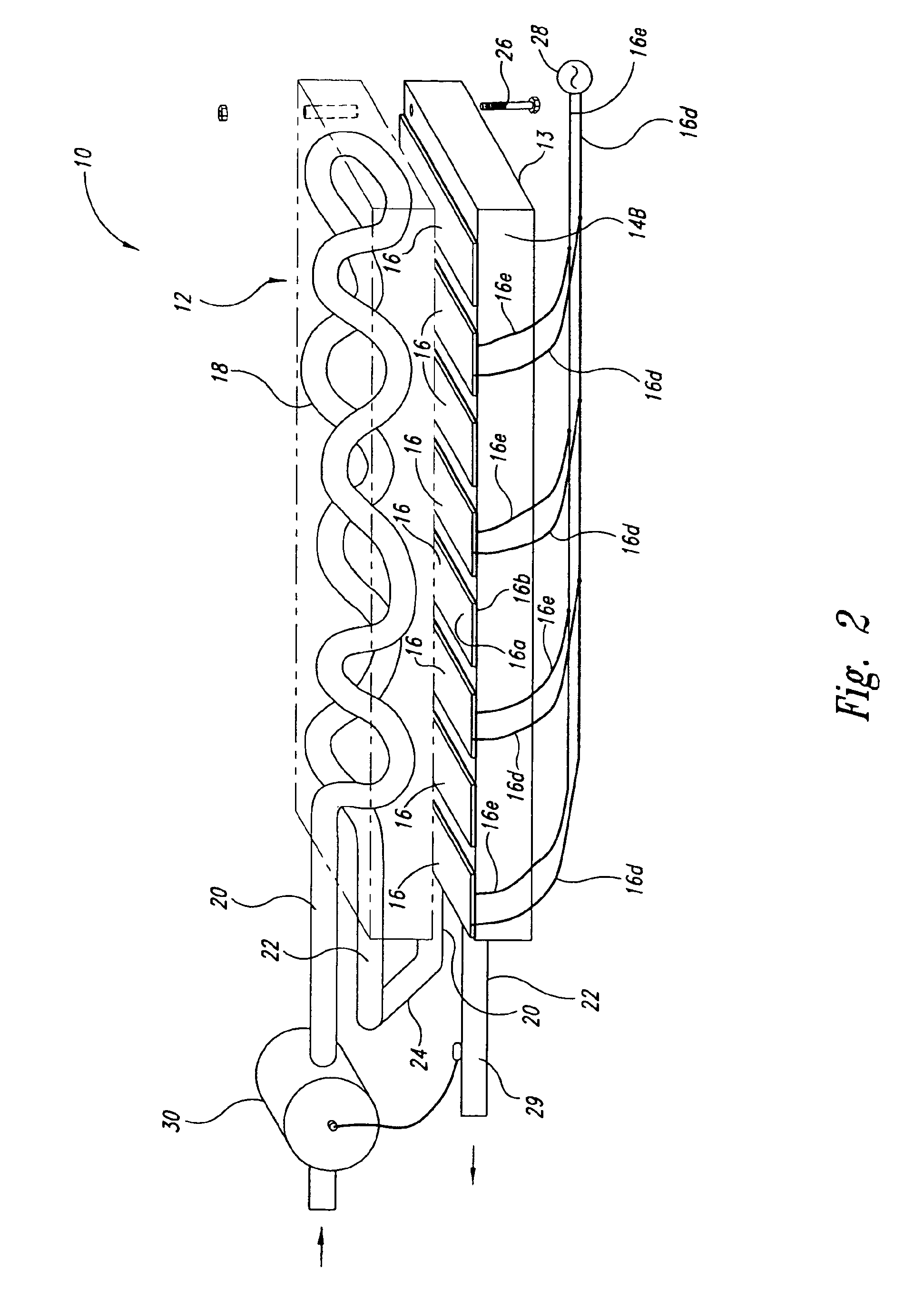
[0019]The heater 10 includes a heat exchanger 12 comprised of two heat exchanger blocks 13 and 14 mounted face-to-face with eight positive temperature coefficient (PTC) heating elements 16 sandwiched between the heat exchanger blocks 13 and 16. In practice, the number of PTC heating elements may vary as required by the application. The number may vary from six or fewer, to fourteen or more.

[0020]Each of the heat exchanger blocks 13 and 14 is formed of a casting of a thermally conductive material, such as aluminum, with an integral fluid heating tube 18 therein, as best shown in FIGS. 2 and 3. Each of the fluid heating tubes 18 has an inlet 20 and an outlet 22. The fluid heating tubes 18 of the heat exchanger blocks 13 and 14 are coupled together in series by a coupler tube 24 connecting the outlet 22 of the fluid heating tube 18 of the first heat exchanger block 13 and the inlet 20 of the fluid heating tube 18 of the second heat exchanger block 14.

[0021]The tubes 18 can be formed wi...


PUM


Abstract

A fluid heater having a first heat exchanger block with a fluid heating tube encased therein, and having a first surface, a second heat exchanger block with a fluid heating tube encased therein and having a second surface adjacent to the first surface. A cavity is formed in the surface of the first block, or, alternatively, formed in each of the surfaces of the first and second blocks. A heating element is positioned within the cavity and completely encapsulated by the first and second blocks. The heating element may include first and second bus plates and a plurality of PTC elements sandwiched between the bus plates in an electrically parallel configuration, each PTC element including first and second conductive plates, and a plurality of positive temperature coefficient heating stones sandwiched between the conductive plates in an electrically parallel configuration.

Description

CROSS-REFERENCE TO RELATED APPLICATION[0001]This application claims the benefit of U.S. Provisional Patent Application No. 60 / 421,296 filed Oct. 25, 2002, which provisional application is incorporated herein by reference in its entirety. This application is a continuation-in-part of U.S. patent application Ser. No. 09 / 878,838, filed Jun. 8, 2001 now U.S. Pat. No. 6,707,987, now pending, which application is incorporated herein by reference in its entirety.BACKGROUND OF THE INVENTION[0002]1. Field of the Invention[0003]This invention relates to a heater for heating fluids. More particularly, to a heater for water or vaporizing liquefied gases such as liquefied petroleum gas.[0004]2. Description of the Related Art[0005]Fluid heaters for the heating and controlled vaporization of liquefied gases are generally known. One electrically heated liquefied petroleum gas (LPG) vaporizer is disclosed in U.S. Pat. No. 4,255,646. Another liquefied gas vapor unit is disclosed in U.S. Pat. No. 4,64...

Claims


Application Information

Patent Timeline
IPC IPC(8): B01D1/00F23K5/22F23K5/02F24H1/12H05B3/42H05B3/14H05B3/50
CPCB01D1/0017F23K5/22F24H1/121H05B3/14H05B3/50F17C2221/035F17C2223/0153H05B2203/02H05B2203/021
Inventor ZIMMER, GEORGE M.
Owner ALGAS SDI INT
Why Eureka
Try Eureka