Curved clamp arm tissue pad attachment for use with ultrasonic surgical instruments
What is Al technical title?
Al technical title is built by PatSnap Al team. It summarizes the technical point description of the patent document.
a tissue pad and clamp arm technology, applied in the field of ultrasonic surgical clamping instruments, can solve the problems of limited ability of single-element end-effector instruments to apply blade-to-tissue pressure, less-than-desired hemostasis and tissue joining, and the use of other ultrasonic surgical instruments
Inactive Publication Date: 2005-10-25
ETHICON ENDO SURGERY INC
View PDF64 Cites 350 Cited by
Summary
Abstract
Description
Claims
Application Information
AI Technical Summary
This helps you quickly interpret patents by identifying the three key elements:
Problems solved by technology
Method used
Benefits of technology
[0012]The present invention meets the above stated needs for an improved curved end-effector. A curved clamp arm for use with an ultrasonic surgical instrument is described. The curved clamp arm includes a proximal end and a distal end, with a top surface extending from the proximal end to the distal end of the curved clamp arm. The top surface comprises at least one hole. The clamp arm includes a bottom surface opposite the top surface, with the bottom surface extending from the proximal end to the distal end of the clamp arm. The bottom surface includes at
Problems solved by technology
While such instruments as disclosed in U.S. Pat. No. 5,263,957 have been found eminently satisfactory, there are limitations with respect to their use, as well as the use of other ultrasonic surgical instruments.
For example, single-element end-effector instruments have limited ability to apply blade-to-tissue pressure when the tissue is soft and loosely supported.
This inability to grasp the tissue results in a further inability to fully coapt tissue surfaces while applying ultrasonic energy, leading to less-than-desired hemostasis and tissue joining.
Generally, however, the Balamuth device, as disclosed in those patents, does not coagulate and cut sufficiently fast, and lacks versatility in that it cannot be used to cut/coagulate without the clamp because access to the blade is blocked by the clamp.
Method used
Image
Click on the blue label to locate the original text in one second.
Reading with bidirectional positioning of images and text.
Examples
Embodiment Construction
[0048]The present invention will be described in combination with ultrasonic instruments as described herein. Such description is exemplary only, and is not intended to limit the scope and applications of the invention. For example, the invention is useful in combination with a multitude of ultrasonic instruments including those described in, for example, U.S. Pat. Nos. 5,938,633; 5,935,144; 5,944,737; 5,322,055, 5,630,420; and 5,449,370.
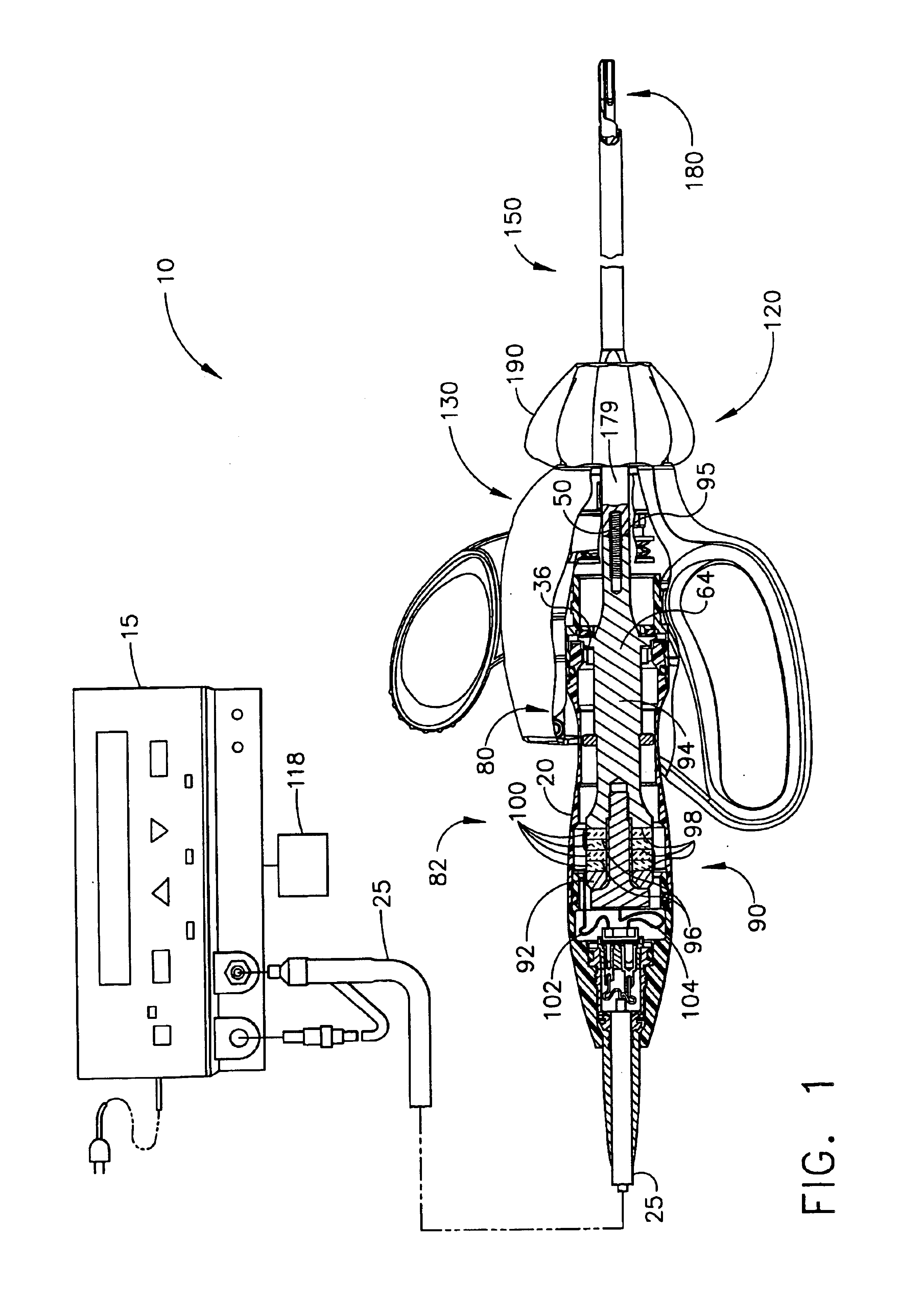
[0049]FIG. 1 illustrates a plan view of an ultrasonic system 10 comprising an ultrasonic signal generator 15 with a sectioned plan view of a sandwich type ultrasonic transducer 82, hand piece housing 20, and clamp coagulator 120 in accordance with the present invention. Clamp coagulator 120 may be used for open or laparoscopic surgery. The ultrasonic transducer 82, which is known as a “Langevin stack”, generally includes a transduction portion 90, a first resonator or end-bell 92, and a second resonator or fore-bell 94, and ancillary components. The...
PUM
Abstract
The present invention relates to ultrasonic surgical clamping instruments and, more particularly, to a curved clamp arm tissue pad attachment for use with ultrasonic surgical instruments. A curved clamp arm for use with an ultrasonic surgical instrument is described. The curved clamp arm includes a proximal end and a distal end, with a top surface extending from the proximal end to the distal end of the curved clamp arm. The top surface comprises at least one hole. The clamp arm includes a bottom surface opposite the top surface, with the bottom surface extending from the proximal end to the distal end of the clamp arm. The bottom surface includes at least one engaging surface, where the hole in the top surface extends from the top surface to the engaging surface of the clamp arm. One embodiment of the curved clamp includes a plurality of the holes in the top surface, and a plurality of the engaging surfaces in the bottom surface, wherein each hole in the top surface extends through the curved clamp arm, terminating at a corresponding engaging surface on the bottom surface. The plurality of holes may also be staggered laterally from the proximal end of the clamp arm to the distal end of the clamp arm.
Description
CROSS REFERENCE TO RELATED PATENT APPLICATIONS[0001]This is a continuation of U.S. patent application Ser. No. 09 / 644,991, filed on Aug. 24, 2000, now abandoned, which is a divisional of U.S. patent application Ser. No. 09 / 412,557 filed on Oct. 5, 1999, now abandoned.FIELD OF THE INVENTION[0002]The present invention relates, in general, to ultrasonic surgical clamping instruments and, more particularly, to a curved clamp arm tissue pad attachment for use with ultrasonic surgical instruments.BACKGROUND OF THE INVENTION[0003]This application is related to the following copending patent applications: application Ser. No. 08 / 948,625 filed Oct. 10, 1997, issued as U.S. Pat. No. 6,068,647 on May 30, 2000; application Ser. No. 08 / 949,133 filed Oct. 10, 1997, issued as U.S. Pat. No. 5,947,984 on Sep. 7, 1999; application Ser. No. 09 / 106,686 filed Jun. 29, 1998, abandoned; application Ser. No. 09 / 337,077 filed Jun. 21, 1999, issued as U.S. Pat. No. 6,214,023 on Apr. 10, 2001; application Ser...
Claims
Application Information
Patent Timeline
Application Date:The date an application was filed.
Publication Date:The date a patent or application was officially published.
First Publication Date:The earliest publication date of a patent with the same application number.
Issue Date:Publication date of the patent grant document.
PCT Entry Date:The Entry date of PCT National Phase.
Estimated Expiry Date:The statutory expiry date of a patent right according to the Patent Law, and it is the longest term of protection that the patent right can achieve without the termination of the patent right due to other reasons(Term extension factor has been taken into account ).
Invalid Date:Actual expiry date is based on effective date or publication date of legal transaction data of invalid patent.