Osteosynthetic bone plate

a technology plate, applied in the field of osteosynthetic bone plate, can solve the problems of increased fracture area, dislocation, and plate cannot be readily adapted to the existing bone geometry,

Inactive Publication Date: 2005-11-01
MEDARTIS AG
View PDF16 Cites 94 Cited by
  • Summary
  • Abstract
  • Description
  • Claims
  • Application Information

AI Technical Summary

Problems solved by technology

However, because of it's rigidity, this plate cannot readily be adapted to the existing bone geometry.
A rigid plate which cannot be sufficiently bent to fit the jaw bone has the effect that the bone fragment less anchored in the jaw is moved toward the plate, and dislocations therefore occur.
Even slight shifts in the fracture area lead to the loss of the interfragment support, which results in greater mobility within the fracture area.
In addition, with the previously available production technology, it would have been extremely complicated to work compression holes into thinner bone plates, for example with the thickness of 1.0 mm.

Method used


Image

  • Osteosynthetic bone plate
  • Osteosynthetic bone plate
  • Osteosynthetic bone plate

Examples


Embodiment Construction

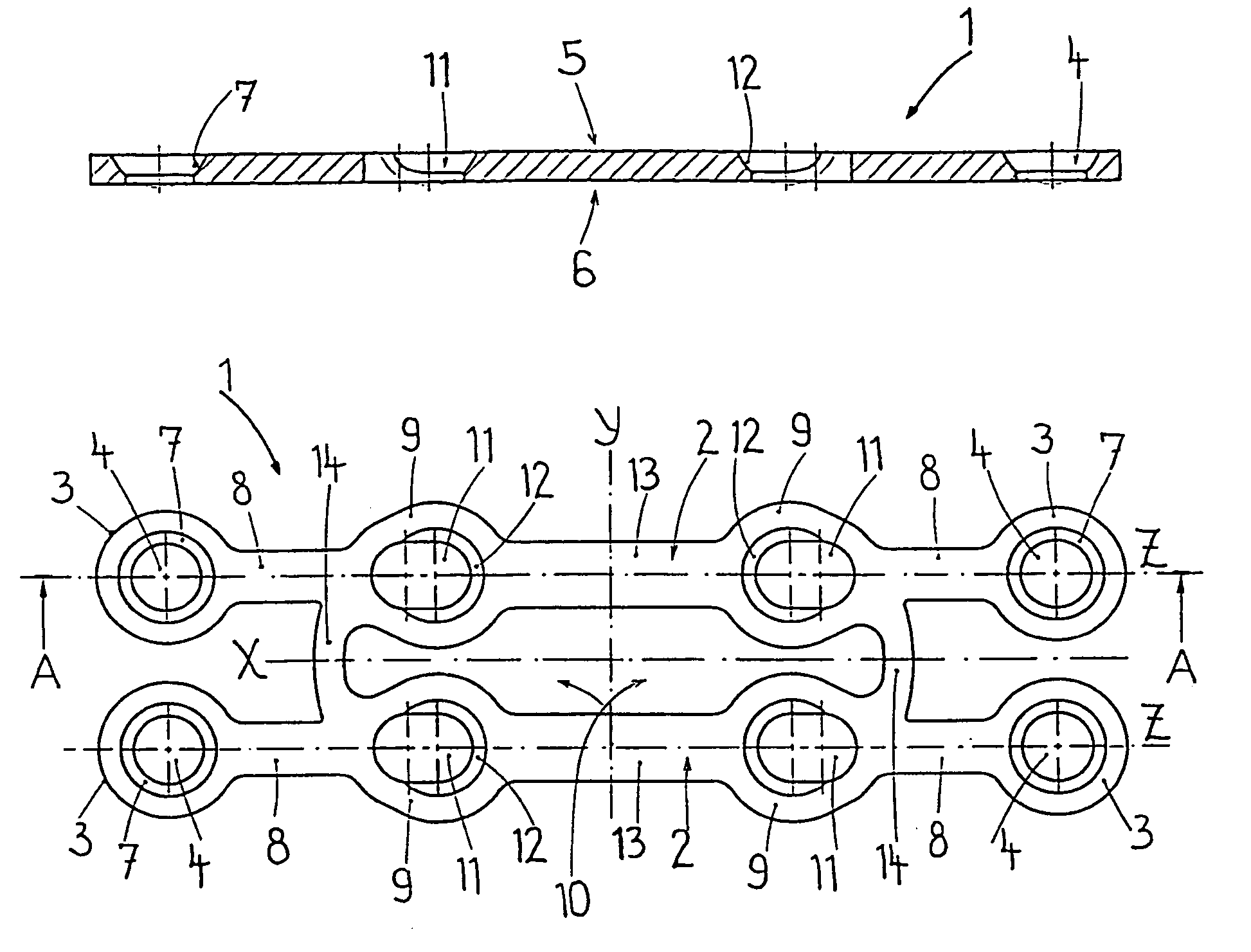
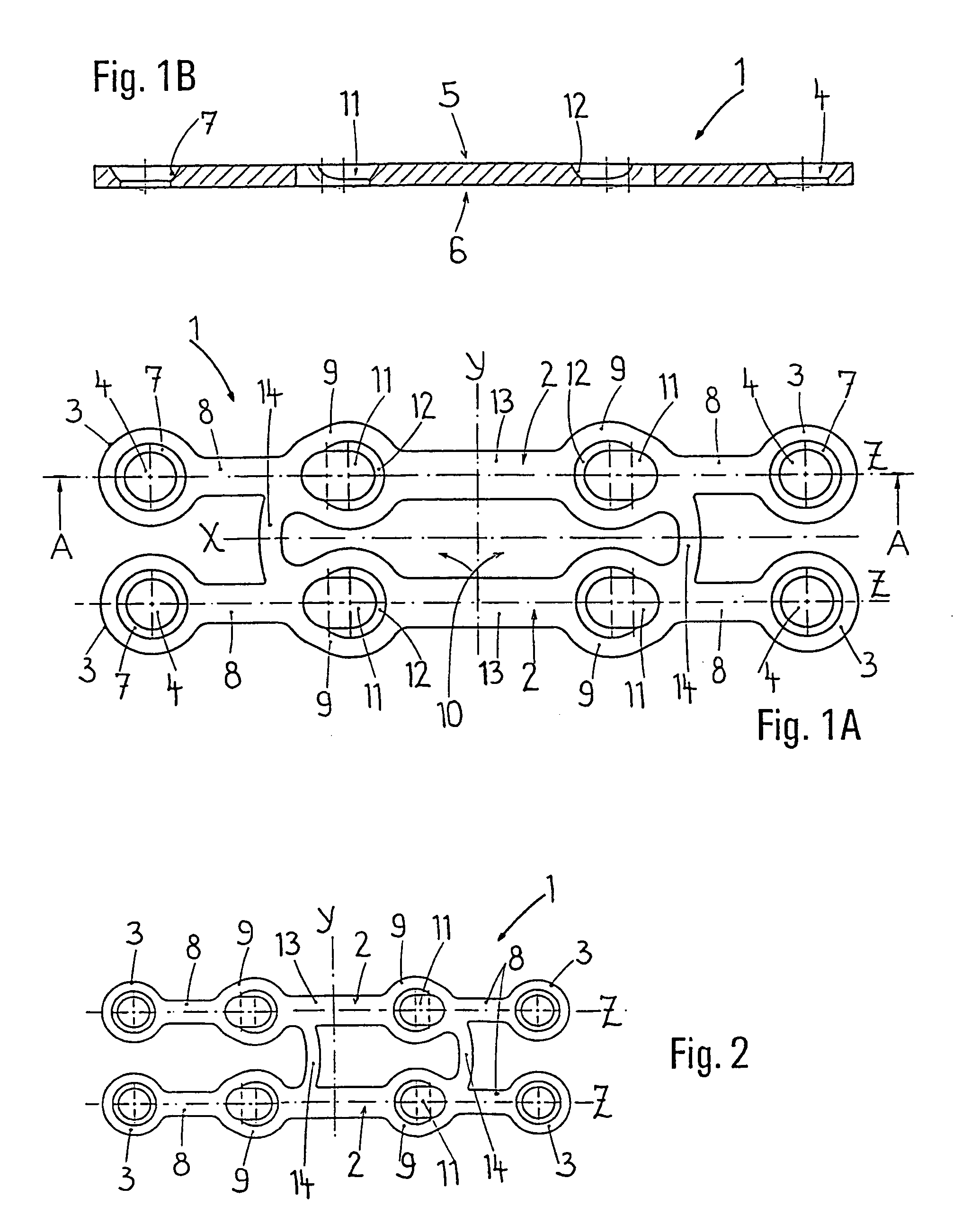
[0028]In the following detailed description of illustrative embodiments of the osteosynthetic bone plate according to the invention, reference is made to the attached drawings.

[0029]As illustrated in FIGS. 1A and 1B, the bone plate 1 constructed symmetrically in relation to the longitudinal axis X and the transverse axis Y has two plate braces 2 running parallel to the longitudinal axis X and spaced apart from one another. The plate braces 2 extend along the brace axes Z. Each plate brace 2 ends at the outside with a disk-shaped plate member 3, at the center of which a cylindrical fixation hole 4 is provided which, on the plate upper side 5, has a countersink 7 for receiving a screw head in a partially recessed manner. The fixation hole 4 opens out cylindrically on the plate lower side 6, which faces toward the bone fragments that are to be joined. From the plate members 3, an attachment strut 8 extends along each of the brace axes Z toward the transverse axis Y.

[0030]The four attac...


PUM


Abstract

An osteosynthetic bone plate has elongated compression cavities containing eccentric countersinks. The plate includes a longitudinal axis, a transverse axis, a plate upper side, and a plate lower side for facing bone fragments. The bone plate also includes a compression element with two plate braces which run substantially parallel to the longitudinal axis. Both plate braces are linked together by bridging struts which intersect the longitudinal axis. A plate brace has an eyelet on at least one of the outer sides of the compression element. Additional eyelets can be positioned in front of this eyelet. A compression cavity is situated in each of said eyelets and a connecting strut, which intersects the transverse axis, extends between the eyelets which are located on each plate brace.

Description

BACKGROUND OF THE INVENTION[0001]Osteosynthetic bone plates for the treatment of fractures, in particular for the reconstruction of mandibular fractures are fitted intraoperatively in order to fix bone fragments together. This may be necessary in osteosynthesis, following accidents in which a bone has shattered into bone fragments, or in orthognathic / maxillofacial treatment for surgical control of abnormal positioning after an osteotomy, and subsequent positional correction of the bone fragments.[0002]Such a bone plate is used principally to span and fix two bone fragments together, one part of the bone plate in each case being connected releasably to a bone fragment. In order to establish the connection between the temporarily fitted bone plate and the bone fragments, the bone plate has through-holes for the insertion of bone screws which engage in the bone fragments. The bone plates should be able to bend in order to correctly match the bone geometry, but at the same time they mus...

Claims


Application Information

Patent Timeline
Patent Type & Authority Patents(United States)
IPC IPC(8): A61B17/68A61B17/80A61B17/00A61B17/58
CPCA61B17/8085A61B17/8004A61B17/8071
Inventor PFEFFERLE, JOACHIMJOOS, ULRICH
Owner MEDARTIS AG
Why Eureka
Try Eureka