
Efficient low dropout linear regulator

a linear regulator and low dropout technology, applied in the field of analog circuits, can solve the problems of increasing the power requirement of the circuit, reducing the efficiency of the circuit, and the method of adding zero compensation, so as to reduce the silicon area and power requirements, the effect of high gain and sufficient bandwidth

Inactive Publication Date: 2005-11-01
HITACHI GLOBAL STORAGE TECH NETHERLANDS BV
View PDF15 Cites 25 Cited by
  • Summary
  • Abstract
  • Description
  • Claims
  • Application Information

AI Technical Summary

Problems solved by technology

To obtain more precise voltage regulation, larger gain is required which inherently makes the feedback less stable.
These two trade-offs, large gain and stability, create a design challenge.
Methods to add zero compensation typically increase the power requirement of the circuit and increase the silicon area, especially if large capacitors are needed in silicon.
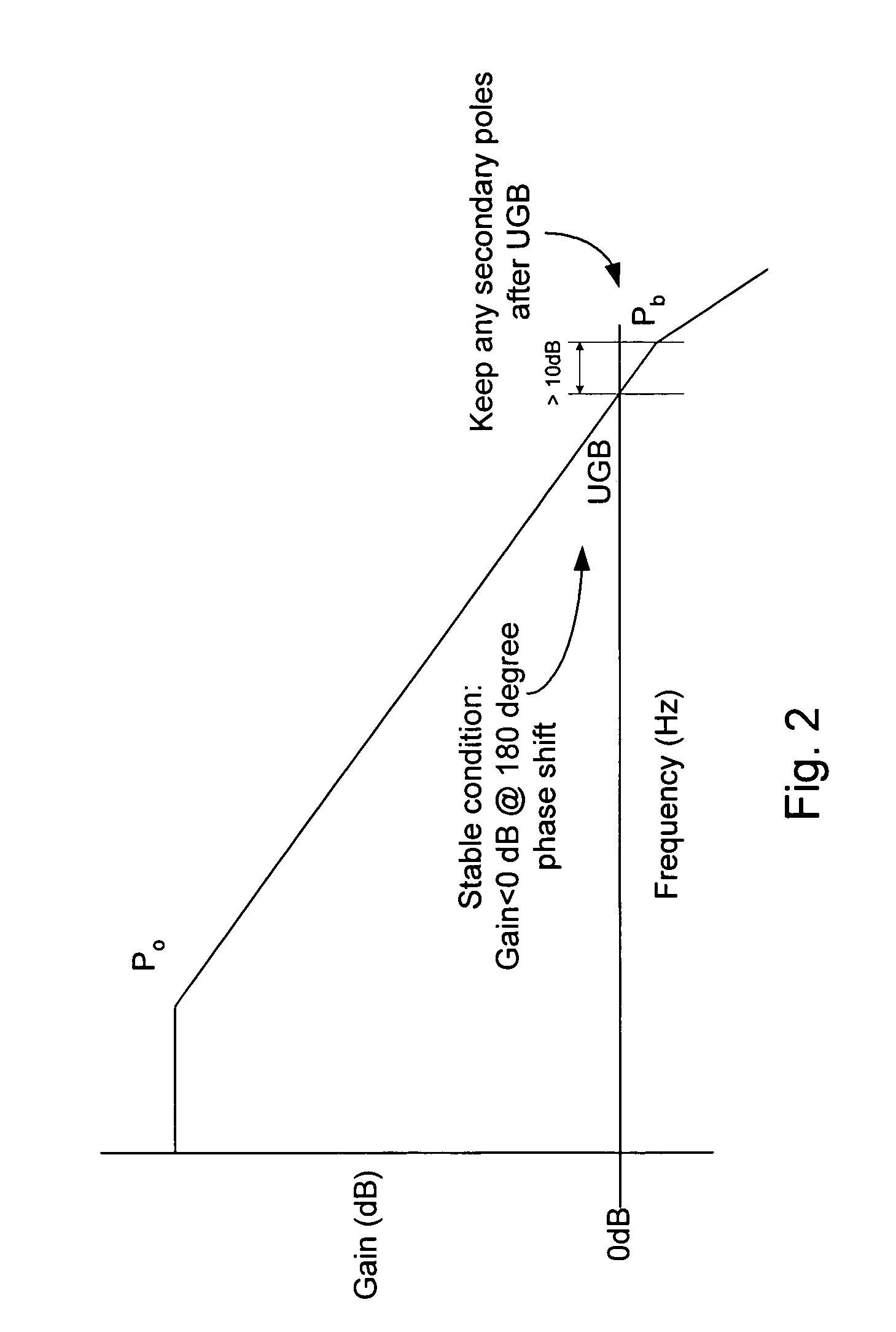
In general, a circuit arrangement can cause stability problems if at least 2 poles exist below the UGB (i.e., less than the unity gain frequency) and no zero compensation is provided.
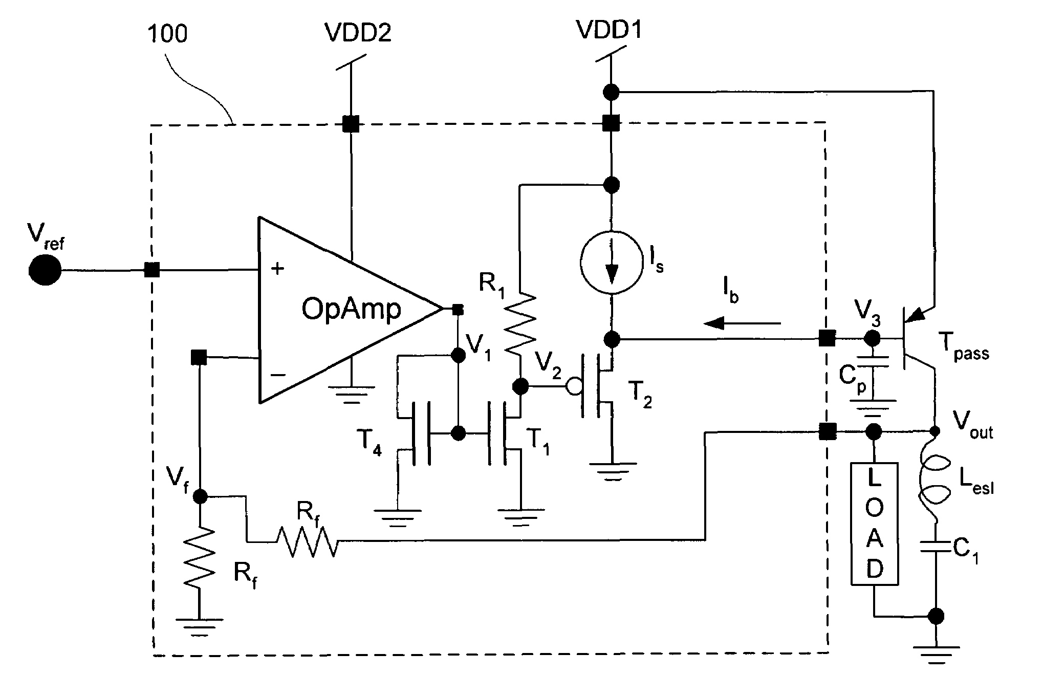
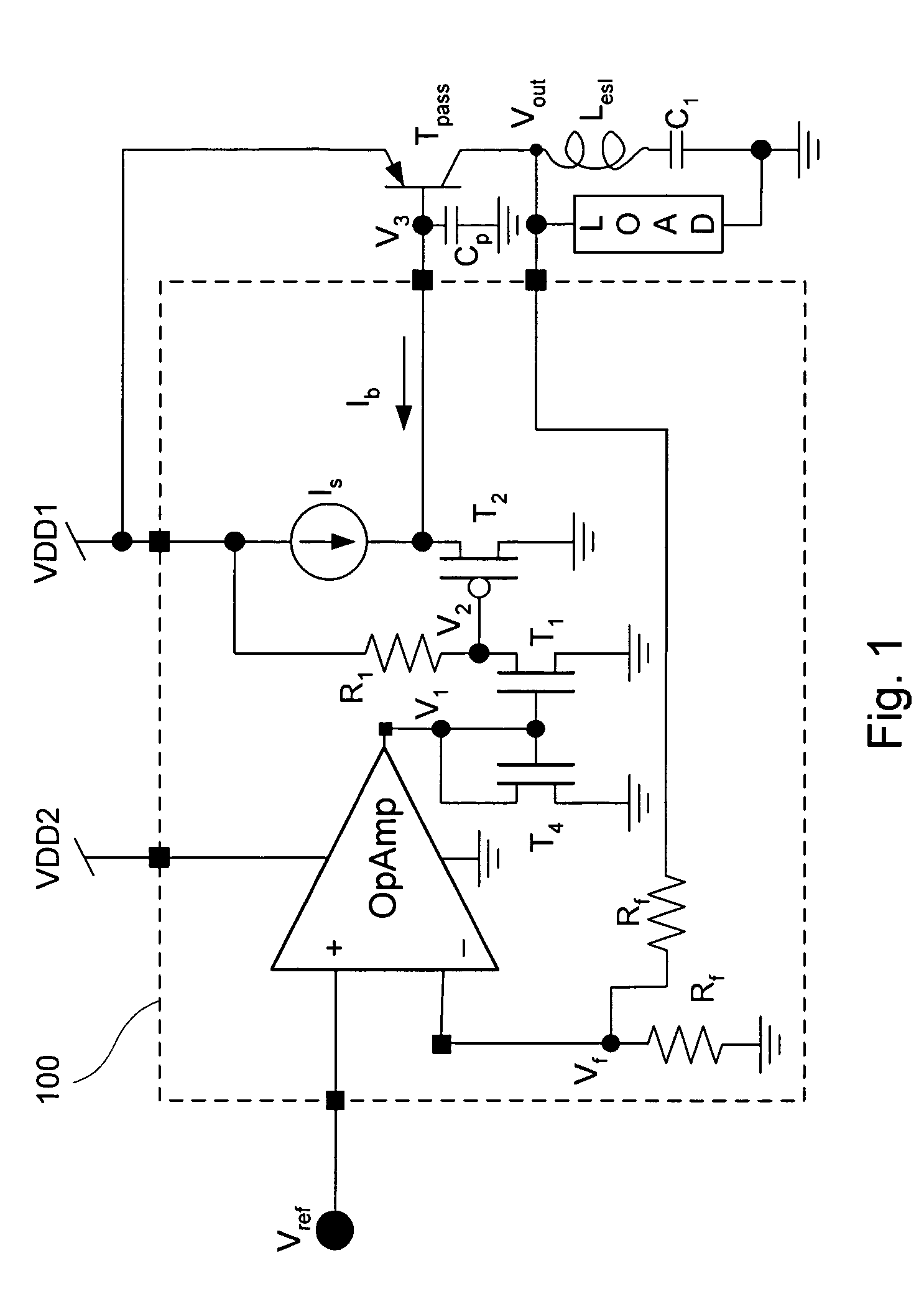
Node V3, however, can be the most difficult node to keep sufficiently low in parasitic capacitance, since it has to drive off the chip and at the base of the Pass transistor resulting in 10's of pF's.
The issue with relying on the ESR of the capacitor is there can be a narrow range of ESR values allowed for a given design.

Method used


Image

  • Efficient low dropout linear regulator
  • Efficient low dropout linear regulator
  • Efficient low dropout linear regulator

Examples


Embodiment Construction

[0018]Circuits embodied in accordance with the present invention keep the secondary poles beyond the UGB. See FIG. 2 for example. Pb represents a secondary pole in the system. As long as the secondary poles are sufficiently beyond the UGB (i.e., greater than the unity gain frequency), the regulator will be stable. There are many places where secondary poles can exist. As can be seen in FIG. 4, for example, nodes V1, V3, Vf, Vout and the OpAmp are potential areas where poles exist. Node V3, however, can be an especially difficult node to keep sufficiently low in parasitic capacitance, since it has to drive off the chip and at the base of the pass transistor Tpass, resulting in capacitance of tens of pF's.

[0019]Referring to FIG. 1, a linear regulator 100 includes an error amplifier comprising an OpAmp circuit. In one embodiment, a single conventional OpAmp device is used. The OpAmp includes a non-inverting input that is coupled to a node which receives a reference voltage, Vref. The O...


PUM


Abstract

A linear voltage regulator circuit includes an external pass transistor that does not rely on internal compensation, provides high gain, and exhibits reduce silicon area and power requirements. Circuits according to the present invention provide sufficient bandwidth with an error amplifier and drive capability to keep any secondary poles sufficiently far from the unity gain bandwidth (UGB) while maintaining good power supply rejection.

Description

CROSS-REFERNCE TO RELATED APPLICATION[0001]The present invention is related to co-pending U.S. application Ser. No. 10 / 788,433, filed Feb. 27, 2004 and is herein incorporated by reference in its entirety for all purposes.BACKGROUND OF THE INVENTION[0002]The present invention relates generally to analog circuits, and in particular low dropout linear regulators and systems which incorporate low dropout linear regulators.[0003]Most linear regulators have feedback which needs some type of stability compensation, either external or internal compensation. To obtain more precise voltage regulation, larger gain is required which inherently makes the feedback less stable. These two trade-offs, large gain and stability, create a design challenge. Other design considerations require low current, reduced silicon area, and good power supply rejection. Many techniques have been implemented for stability compensation. The following patents constitute a sampling of conventional solutions: U.S. Pat....

Claims


Application Information

Patent Timeline
Patent Type & Authority Patents(United States)
IPC IPC(8): G05F1/40G05F3/26G05F3/08G05F1/10G05F1/575H03F3/345H03F3/45
CPCG05F1/575H03F3/345H03F3/45475
Inventor POSS, JOE M.
Owner HITACHI GLOBAL STORAGE TECH NETHERLANDS BV
Learn More