
Automated electronic calibration apparatus

a calibration apparatus and electronic technology, applied in the field of radio frequency and microwave network analyzers, can solve the problems of inability to correct random errors, noise and repeatability of connectors, and inability to repeat measurement calibration and error correction, and systematic errors, such as tracking and crosstalk, are the most significant errors, and require new measurement calibrations

Active Publication Date: 2005-11-15
KEYSIGHT TECH
View PDF12 Cites 30 Cited by
  • Summary
  • Abstract
  • Description
  • Claims
  • Application Information

AI Technical Summary

Benefits of technology

The present invention provides a method for testing a device without disconnecting the calibration modules used for the test. This is achieved by connecting the first calibration module to the device under test, the network analyzer, and the second calibration module to the device under test and the network analyzer. The measurement calibration and testing are performed without disconnecting the first and second ports of the first calibration module or the first and second ports of the second calibration module. This method simplifies the testing process and reduces the risk of damage to the device under test.

Problems solved by technology

Random errors, such as noise and connector repeatability are non-repeatable and not correctable by measurement calibration and error correction.
Systematic errors, such as tracking and crosstalk, are the most significant errors in most network analyzer measurements.
These systematic errors may drift with time and temperature and therefore require new measurement calibrations to maintain error corrected measurement accuracy.
Systematic errors are due to system frequency response, isolation between the signal paths, and mismatch in the test setup.
Frequency response errors (transmission and reflection tracking) result from the difference of the test signal path and receiver with respect to the reference signal path and receiver that are a function of frequency.
Isolation errors result from energy leakage between signal paths in measurements.
This leakage is due to crosstalk.
In reflection measurements, the leakage is also due to imperfect directivity.
Mismatch errors result from differences between the port impedance of the device under test (DUT) and the port impedance of the network analyzer.
If the DUT is not connected directly to the ports, the mismatch errors due to cables, adapters, etc. are considered part of the source or load match errors.

Method used


Image

  • Automated electronic calibration apparatus
  • Automated electronic calibration apparatus
  • Automated electronic calibration apparatus

Examples


Embodiment Construction

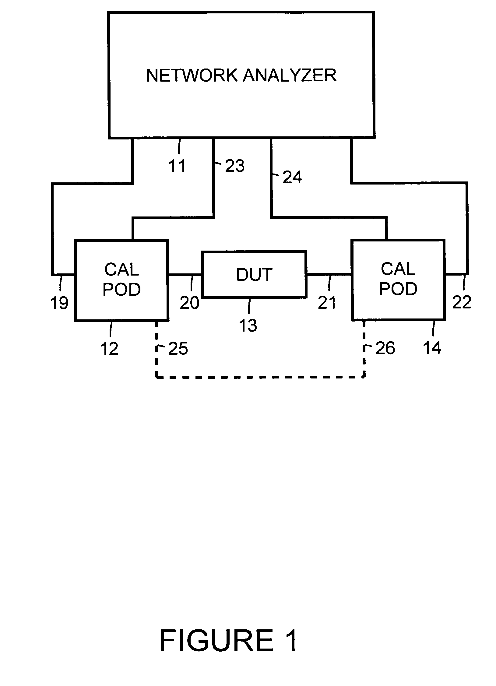
[0019]FIG. 1 is a simplified block diagram showing a network analyzer 11 configured to perform tests on a device under test (DUT) 13. Network analyzer 11 is, for example a radio frequency (RF) or microwave vector network analyzer (VNA).

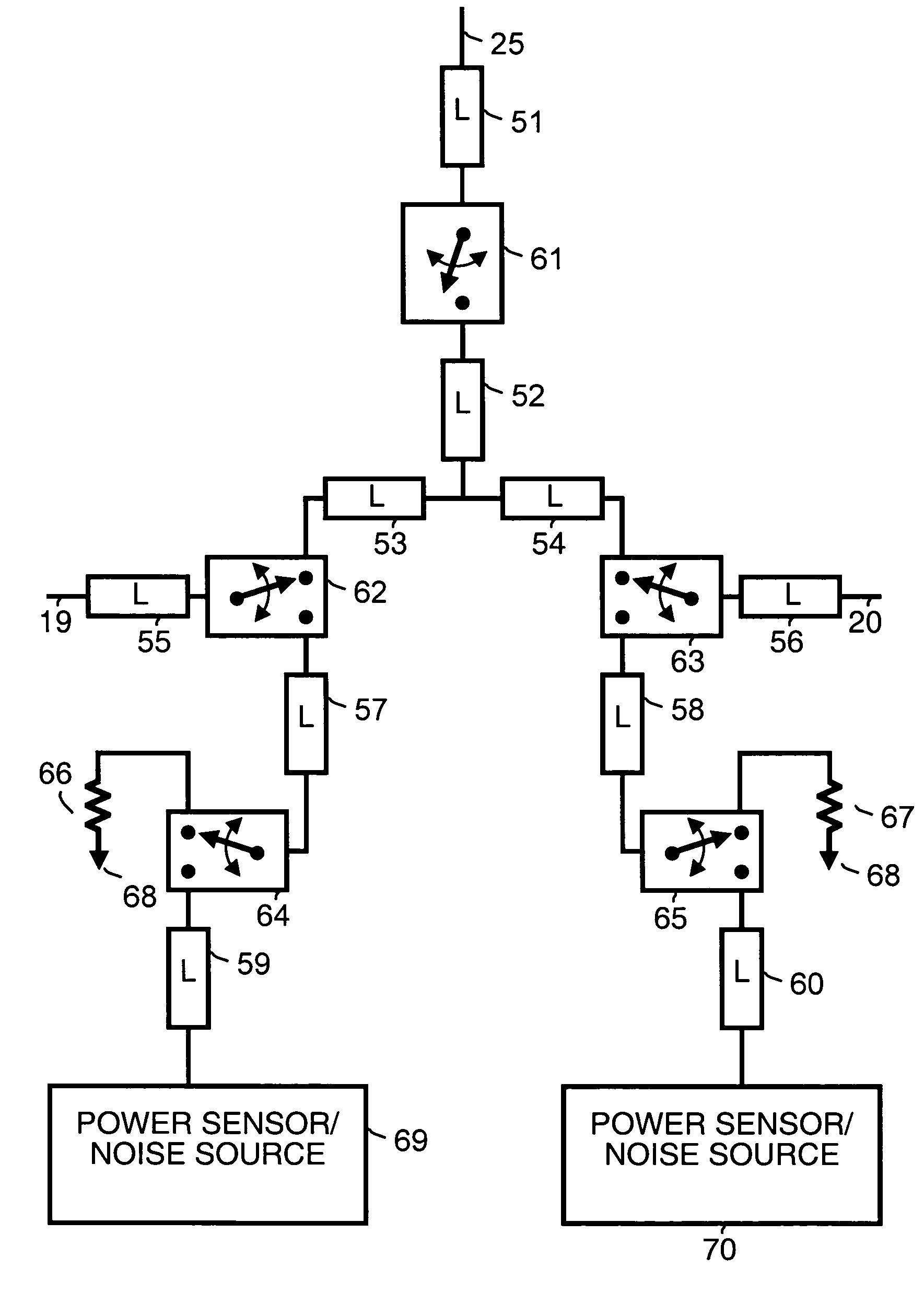
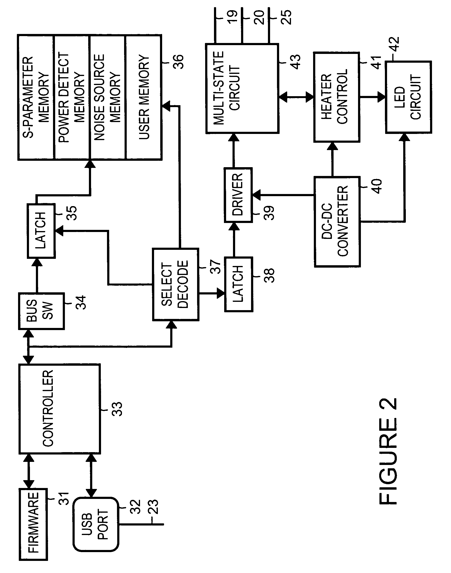
[0020]A calibration module (calpod) 12 and a calibration module (calpod) 14 are connected on either side of DUT 13. Calibration module 12 and calibration module 14 are electronically controlled network analyzer calibration devices with switchable input / output stage, power detector and noise source. Calibration module 12 and calibration module 14 remain connected to DUT 13 during testing, allowing network analyzer 11 to self-calibrate during testing of DUT 13. Time and temperature drift errors are reduced when measurement calibration can be performed whenever is desired without any connecting and disconnecting of the calibration modules.

[0021]A port 19 of calibration module 12 is connected to a port of network analyzer 11. A port 20 of calibration modu...


PUM


Abstract

Testing is performed on a device under test. A first port of a first calibration module is connected to the device under test. A second port of the first calibration module is connected to a network analyzer. A first port of a second calibration module is connected to the device under test. A second port of the second calibration module is connected to the network analyzer. A measurement calibration and testing are performed without disconnecting the first port and the second port of the first calibration module and without disconnecting the first port and the second port of the second calibration module.

Description

BACKGROUND[0001]The present invention concerns radio frequency and microwave network analyzers and pertains particularly to an automated electronic calibration apparatus.[0002]A network analyzer typically integrates a synthesized signal source with built-in signal separation devices, receivers, a display and a processor.[0003]Measurement calibration is a process that characterizes the systematic errors of a network analyzer. This information can be used to improve measurement accuracy by using error correction arrays during signal processing to compensate for systematic measurement errors. Measurement calibration is also called Cal, a short form of calibration. Error correction is also called accuracy enhancement. Measurement errors are classified as random and systematic errors. Random errors, such as noise and connector repeatability are non-repeatable and not correctable by measurement calibration and error correction.[0004]Systematic errors, such as tracking and crosstalk, are t...

Claims


Application Information

Patent Timeline
Patent Type & Authority Patents(United States)
IPC IPC(8): G01R35/00G01R27/28
CPCG01R27/28G01R35/005
Inventor LIU, JAMES C.WONG, KENNETH H.SHIMON, ROBERT L.CASSANEGO, PAUL E.SUNDARAM, SRINIVAS M.TORIN, SHIGETSUNEHAWKINS, RICHARD R.
Owner KEYSIGHT TECH
Learn More