Remote camera positioner

a remote camera and positioner technology, applied in the field of apparatus, can solve the problems of limiting the application of the apparatus, pointing or positioning the camera underwater is subject to drag and fluid infiltration forces, and the motion imaging of underwater film and video is substantially complicated

Inactive Publication Date: 2005-11-15
JONES RICHARD A
View PDF8 Cites 38 Cited by
  • Summary
  • Abstract
  • Description
  • Claims
  • Application Information

AI Technical Summary

Problems solved by technology

Underwater motion imaging, both film and video, is substantially complicated by an inhospitable environment.
The pointing or positioning of a camera underwater is subject to both significant drag and fluid infiltration forces.
While some attempts have been made to devise apparatus capable of remotely positioning a camera underwater, they have been limited to apparatus capable of dipping a camera housing a few inches beneath the surface, then tilting the lens above the surface.
Such apparatus is not completely submersible.
A few drops of water in the wrong place can render it inoperable.
Thus, present-day underwater photography is skilled, labor-intensive and cannot realize the advantages of remote operation, which permits the cameraman to give his complete concentration to the images being captured, that are commonly utilized in above-surface photography.

Method used


Image

  • Remote camera positioner
  • Remote camera positioner
  • Remote camera positioner

Examples


Embodiment Construction

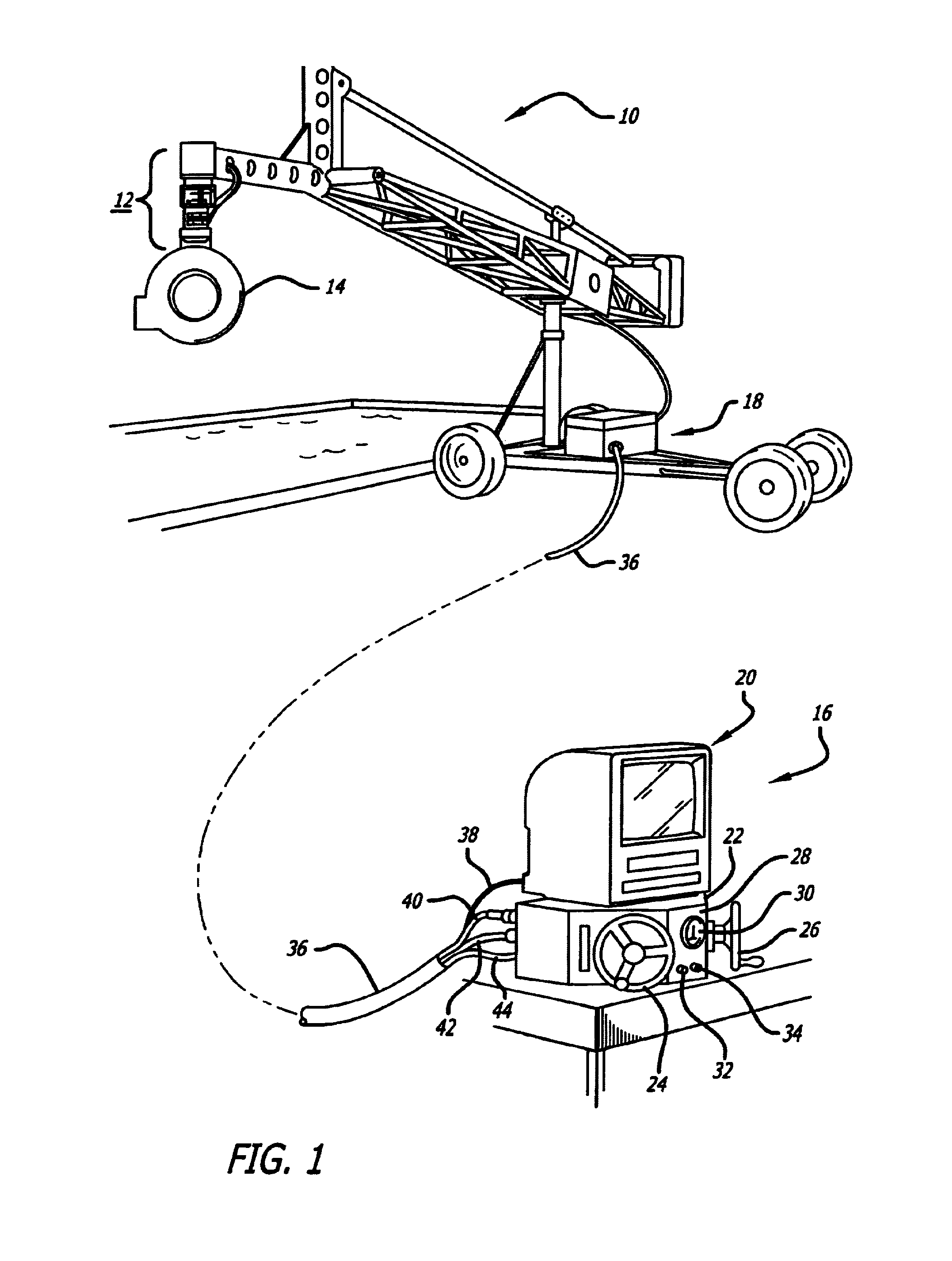
[0018]Turning to the drawings, FIG. 1 is a perspective view of the overall invention. As shown, the apparatus of the invention is mounted to a mobile counterbalanced boom 10 of a type that is conventionally employed to position a film or video camera.

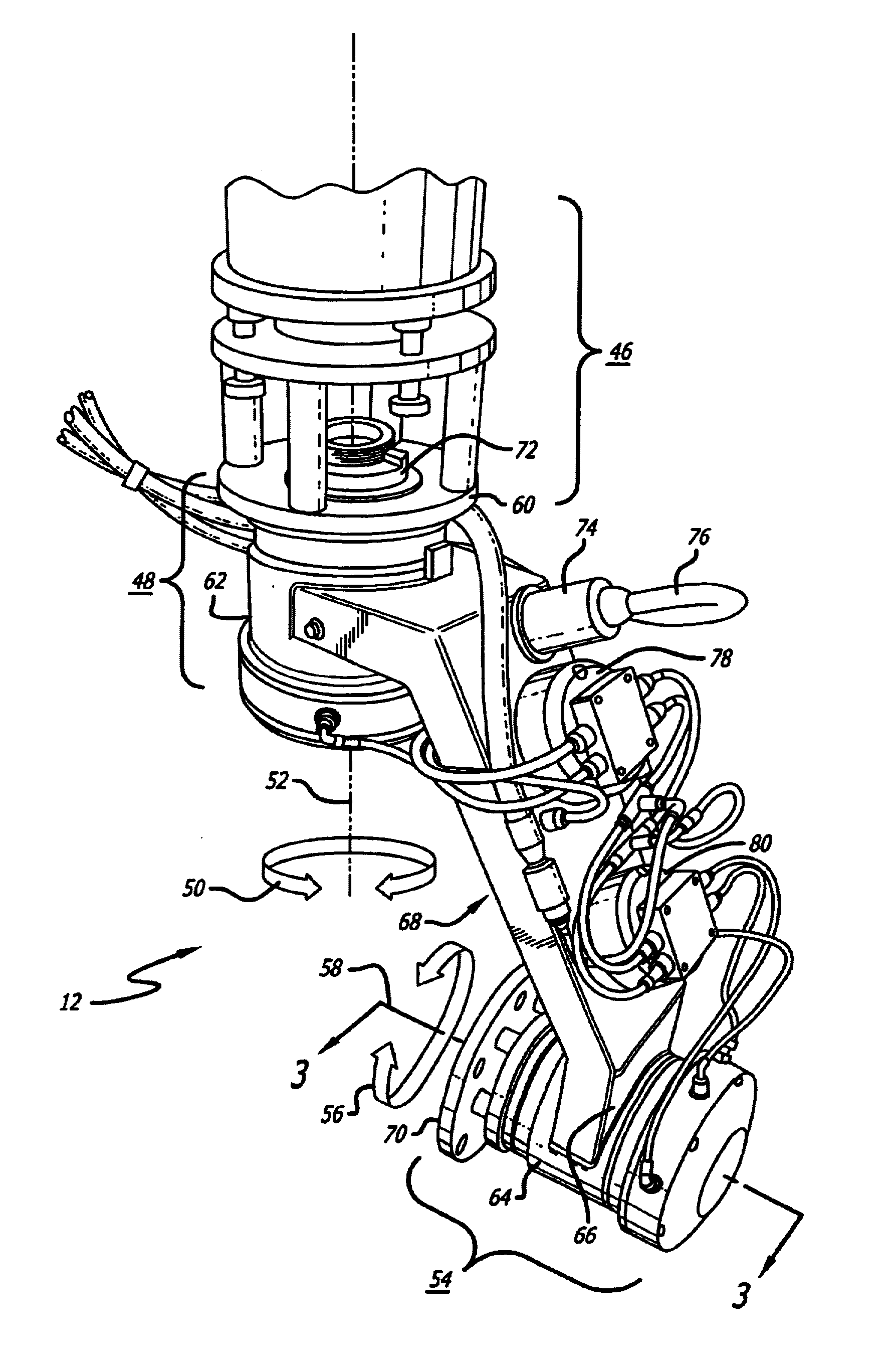
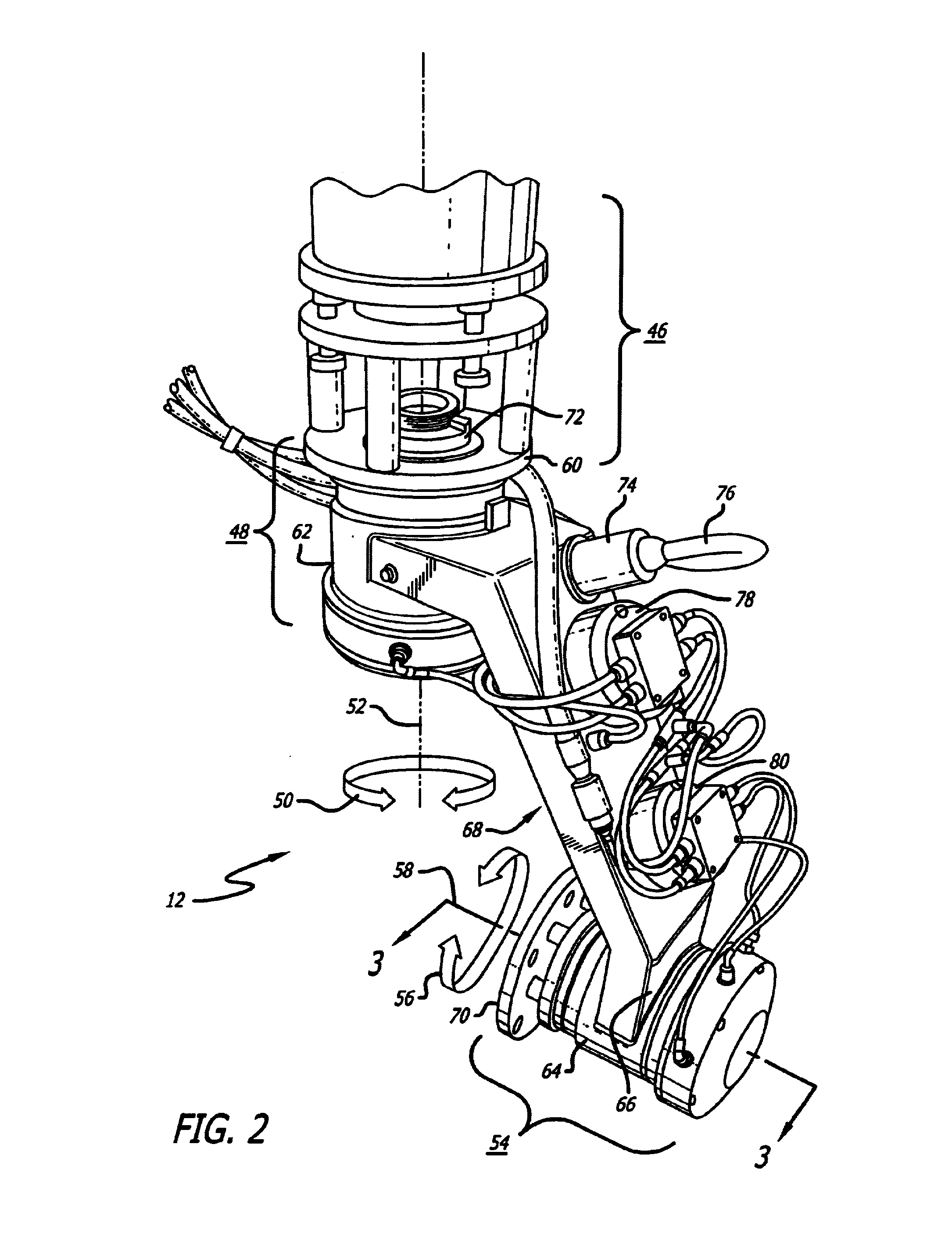
[0019]The invention comprises a positioning structure 12 engaged to the distal end of the boom 10. Such structure 12 is provided for supporting and pointing a camera (not shown) that is housed within a conventional watertight camera cover 14.

[0020]The positioning structure 12 is hydraulically actuated and responsive to both hydraulic and electrical signals that are input at the command of a control unit 16. A hydraulic unit 18 houses apparatus for pumping and storing fluid under pressure.

[0021]Referring back to the control unit 16, a video monitor 20 provides the operator with a real time view of the camera output. A control box 22, upon which the monitor 20 is seated, includes hydraulic control wheels 24 and 26 for adjusting the attitu...


PUM


Abstract

Apparatus for remotely controlling the positioner of a camera head. At least one hydraulically-actuated positioner for rotating the camera head with respect to an axis is fixed to the camera head and to a camera support device, such as a camera boom. The positioner includes an output shaft whose angular displacement is responsive to fluid flows transmitted through a pair of associated hydraulic lines. A valve is associated with each positioner and controls the flow of fluid within the pair of positioner hydraulic lines. A control unit receives and processes inputs provided by a camera operator (observing the camera's field-of-view on a monitor) and outputs generated by the system so that the necessary adjustments may be controlled by the valves to assume smooth camera movements in either an aquatic environment or otherwise.

Description

BACKGROUND[0001]1. Field of the Invention[0002]The present invention relates to apparatus for remotely controlling the attitude of a television camera. More particularly, this invention pertains to apparatus suitable for the remote positioning of a film or video camera in an underwater environment.[0003]2. Description of the Prior Art[0004]Underwater motion imaging, both film and video, is substantially complicated by an inhospitable environment. The pointing or positioning of a camera underwater is subject to both significant drag and fluid infiltration forces.[0005]While some attempts have been made to devise apparatus capable of remotely positioning a camera underwater, they have been limited to apparatus capable of dipping a camera housing a few inches beneath the surface, then tilting the lens above the surface. Such apparatus is not completely submersible. A few drops of water in the wrong place can render it inoperable.[0006]As a result, underwater film and video photography ...

Claims


Application Information

Patent Timeline
Patent Type & Authority Patents(United States)
IPC IPC(8): B23Q15/00H04N9/44H04N9/47H04N5/225F16M11/12F16M11/18H04N5/232
CPCF16M11/105F16M11/12F16M11/125F16M11/18F16M11/2064H04N5/2251H04N5/2252H04N5/23203H04N23/50H04N23/51H04N23/66H04N23/695
Inventor JONES, RICHARD A.
Owner JONES RICHARD A
Why Eureka
Try Eureka