Volume-responsive loudness compensation circuits, systems, and methods

a volume-responsive, compensation circuit technology, applied in the direction of frequency response correction, gain control, electrical transducers, etc., can solve the problems of physical limitations, complexity, cost, and limitations of audio systems and compensation systems, and may not work in a relatively inexpensive audio system that has poor (or no) response at such low frequencies

Inactive Publication Date: 2005-11-15
TEXAS INSTR INC +1
View PDF12 Cites 55 Cited by
  • Summary
  • Abstract
  • Description
  • Claims
  • Application Information

AI Technical Summary

Benefits of technology

[0011]In the preferred embodiment, there is an audio compensation system for producing a sound compensated output signal. The system comprises a volume control circuit for producing a volume-adjusted signal by applying a volume adjustment to an audio signal in response to a volume setting, wherein the sound compensated output signal i...

Problems solved by technology

The actual circuit implementations of the sound compensation methodologies described above also have varied in the art based on various criteria, and many of these implementations have limitations.
As another example, there often are considerations of the physical limitations, complexity, and costs of audio systems and compensation systems.
However, such an approach may not be workable in a relatively inexpensive audio system that has poor (or no) response at such low frequencies.
As a result, some of the prior approaches may be implemented at slightly higher frequencies, but in these alternatives there is the possibility that higher frequency signals, such as vocal frequencies, may be modified in a manner that is undesirable or inconsistent with the human ear's original failure to accurately perceive the lower frequencies.
As still another example, differential loudness ...

Method used


Image

  • Volume-responsive loudness compensation circuits, systems, and methods
  • Volume-responsive loudness compensation circuits, systems, and methods

Examples


Embodiment Construction

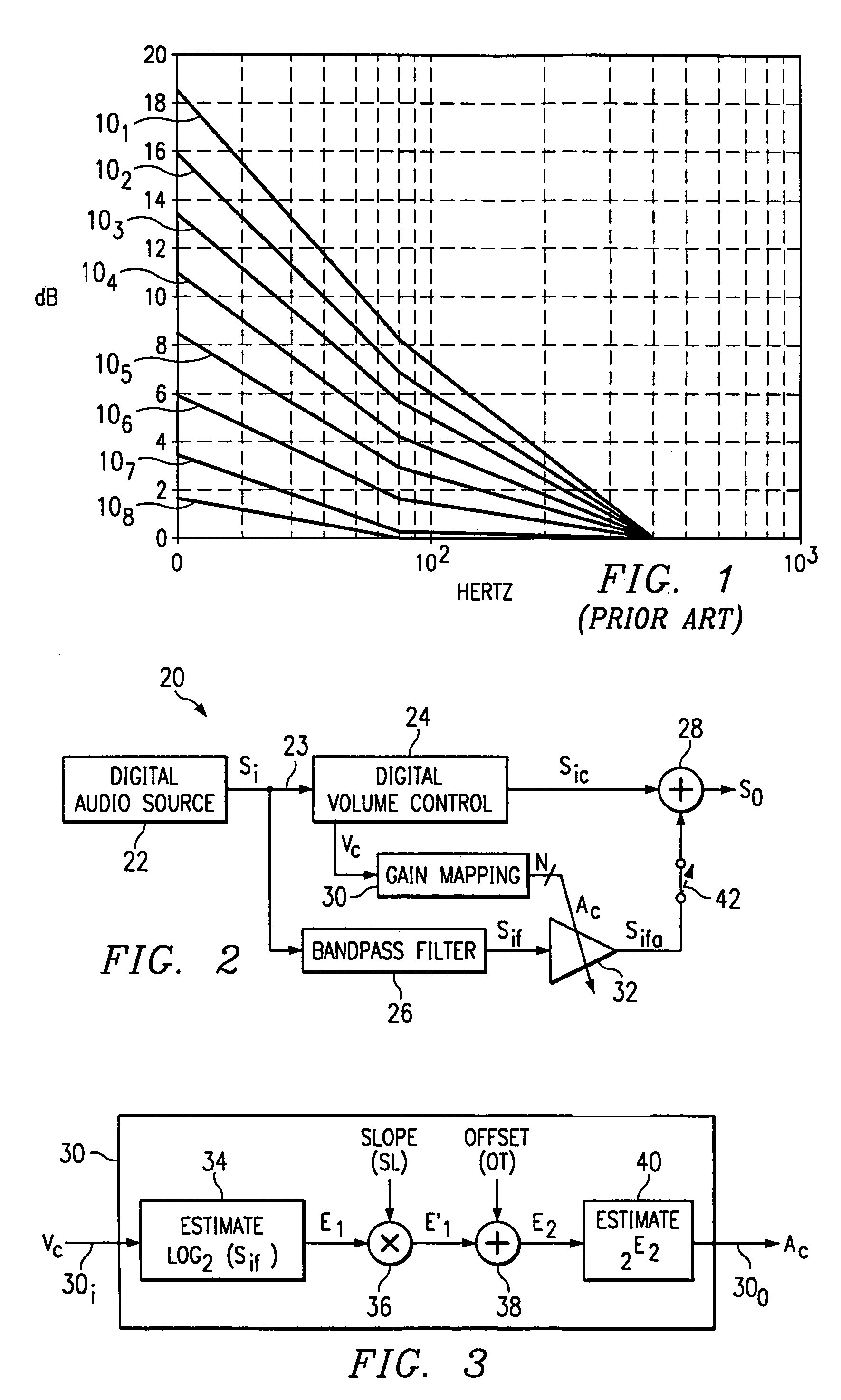
[0015]FIG. 1 was discussed above in the Background Of The Invention section of this document and the reader is assumed familiar with the details of that discussion.

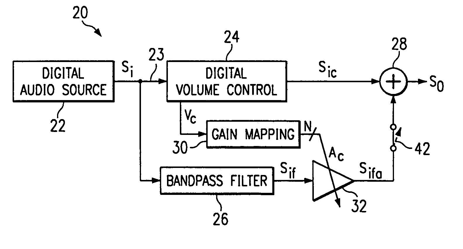
[0016]FIG. 2 illustrates a block diagram of a differential loudness compensation circuit 20 according to the preferred embodiment. By way of introduction, a few observations are made. As a first observation, the blocks of FIG. 2 are by way of example to discuss the functionality and method of operation of circuit 20. Thus, the blocks of FIG. 2 may be combined or further subdivided by one skilled in the art unless stated to the contrary in this document. In addition, the blocks of FIG. 2 may be implemented by one skilled in the art using various different circuits or via a dedicated integral device or a signal processor. As a second observation, only a single channel is shown in FIG. 2 to simplify the illustration and following discussion, while one skilled in the art will appreciate that the inventive teachings of this do...


PUM


Abstract

An audio compensation system (20) for producing a sound compensated output signal (So). The system comprises a volume control circuit (24) for producing a volume-adjusted signal (Sic) by applying a volume adjustment to an audio signal in response to a volume setting, wherein the sound compensated output signal is responsive to the volume-adjusted signal. The system also comprises circuitry (26, 30, 32) for producing an amplified signal (Sifa) by amplifying a selected bandwith of signals in response to the volume setting. The sound compensated output signal is also responsive to the amplified signal.

Description

CROSS-REFERENCES TO RELATED APPLICATIONS[0001]This application is a continuation-in-part application of U.S. patent application Ser. No. 09 / 421,417, filed Oct. 19, 1999, entitled “Configurable Digital Loudness Compensation System And Method,” having the same inventor as the present application, and incorporated herein by this reference.STATEMENT REGARDING FEDERALLY SPONSORED RESEARCH OR DEVELOPMENT[0002]Not Applicable.BACKGROUND OF THE INVENTION[0003]The present embodiments relate to digital sound processing, and are more particularly directed to digital loudness compensation.[0004]For decades it has been understood that the human listener's perception of loudness varies with frequency when sound pressure (i.e., volume) is held constant. Specifically, for a fixed sound pressure, bass frequencies are perceived at a lower loudness than are treble frequencies. As a result, various sound processing approaches have arisen to process pre-recorded sound so that it is played back in a modif...

Claims


Application Information

Patent Timeline
IPC IPC(8): H03G3/00H03H17/00H03G9/00H04R3/04H03G5/00
CPCH03G5/005
Inventor ALLRED, RUSTIN W
Owner TEXAS INSTR INC
Why Eureka
Try Eureka