
Utility light

Inactive Publication Date: 2005-11-22
RALLY MFG
View PDF5 Cites 15 Cited by
  • Summary
  • Abstract
  • Description
  • Claims
  • Application Information

AI Technical Summary

Benefits of technology

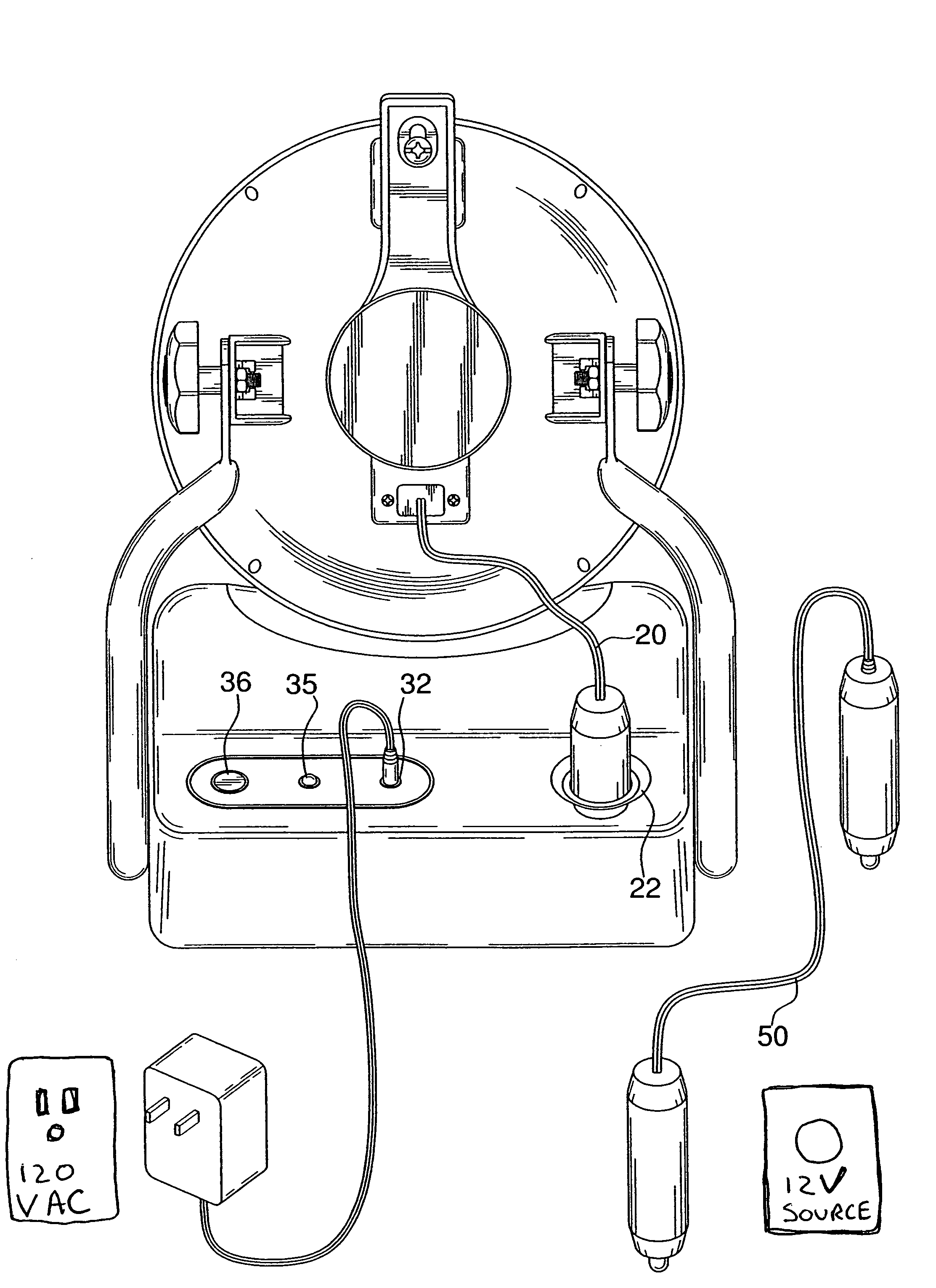
[0006]The present invention is directed to a portable utility light that may be operated by multiple sources of power. A base support contains a rechargeable battery. A light assembly is pivotally supported on the base support and is electrically connected to the rechargeable battery through a power cord removably connected to a first connector portion of the base support. The power cord is adapted for selective connection to an auxiliary power source such as a cigarette lighter receptacle of an automobile to provide a direct auxiliary power source for the light assembly. A power supply mechanism is also connected to a second connection portion of the base support to provide another power source to either recharge the rechargeable battery power the light assembly. The rechargeable batter is connected to the first and second connection portions of the base support in parallel to facilitate the ability for multiple sources of power for recharging the battery. A male / male plug cord may be employed to utilize the auxiliary power source to recharge the battery through the first connection portion. The work light thus provides a multiple sources of power for the light as well as multiple sources of power for recharging a battery disposed within the base support. The physical configuration of the utility light also provides a portable sturdy adjustable light source.

Problems solved by technology

However, such AC powered lights suffer from the drawback that they must be connected to a permanent source of AC power such as common electrical outlets and are not portable are useable in remote locations.
However, the batteries must be replaced when consumed.

Method used


Image

  • Utility light
  • Utility light
  • Utility light

Examples


Embodiment Construction

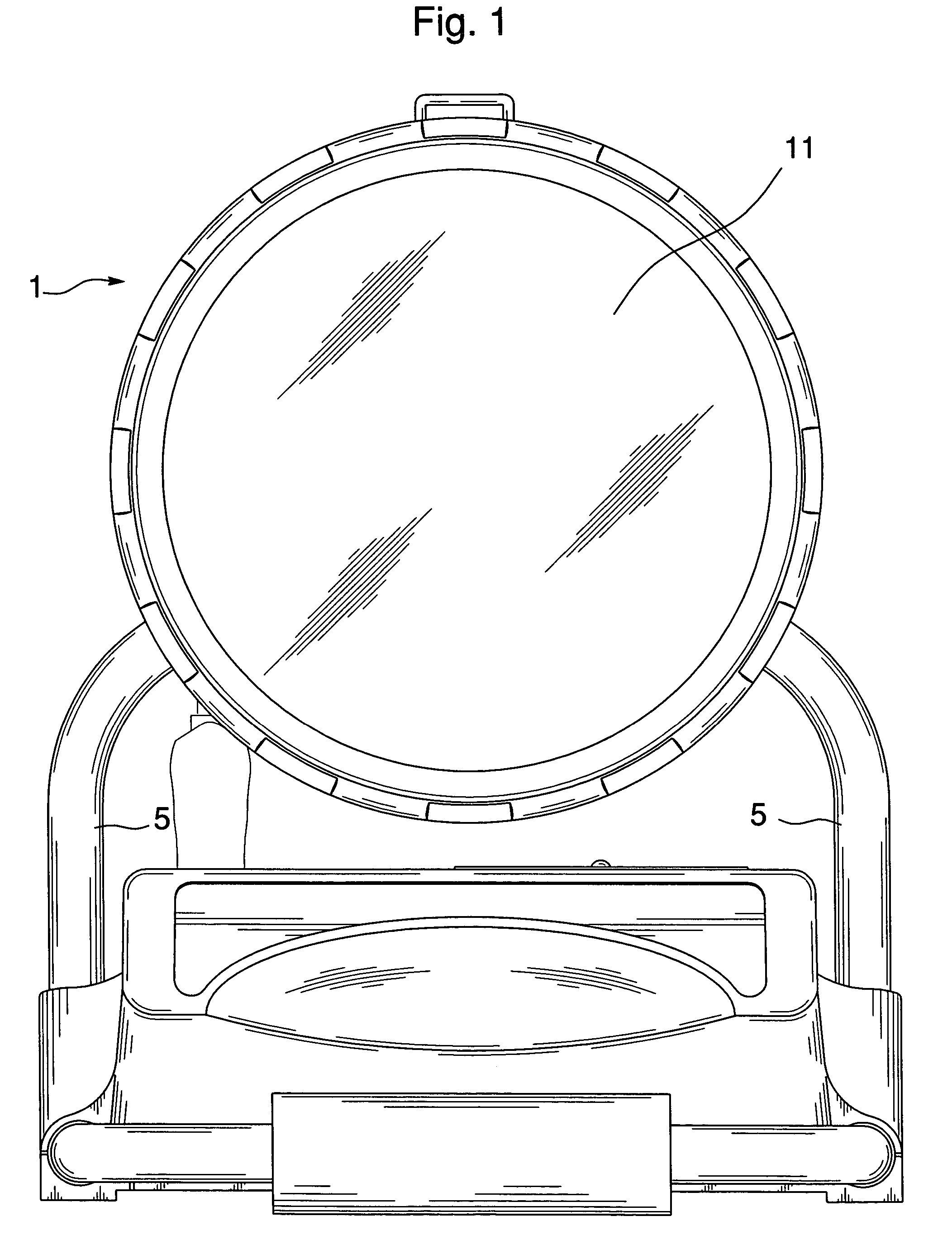
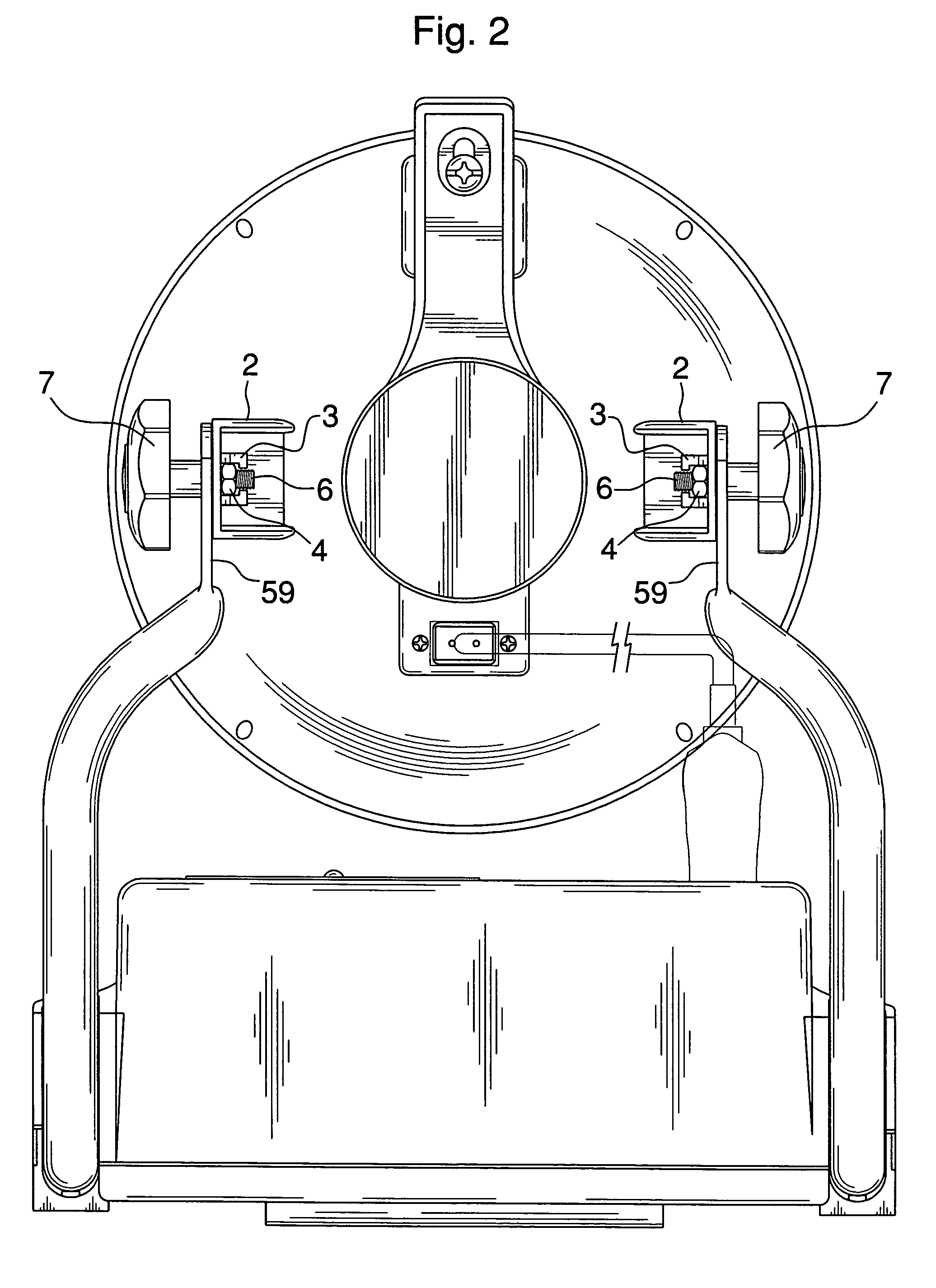
[0016]Referring to FIG. 3, the present a light assembly 1 is pivotally connected to a pair of support arms 5 which in turn extends through apportion of a base support 9. Preferably the supporting arms include a single piece U-shaped like metal pipe that extends through a portion of the base support 9 and back up towards the light assembly 1. As best viewed in FIG. 7, the support arm 5 extends through a grooved recess formed in the base support 9. A bottom plate 10 is removably secured to the bottom of the base support 9 to allow for installation and removal of the support arm 5. The light assembly 1 with lens 11 is simply rotatably connected to the upper terminal ends of the support arm 5. Referring to FIG. 2, the light assembly 1 has a pair of brackets 2 extending from a light housing for connection to the support arms. The brackets have a grooved recess 3 formed thereon for non-rotatably containing a nut 4. The upper end of the support arms have flattened ends 5a with a hole which...


PUM


Abstract

A portable utility light includes base support with a rechargeable battery. A light assembly is electrically connected to the rechargeable battery in the base support through a power cord removably connected to the base support. The power cord is adapted for selective connection to an auxiliary power source to provide a direct auxiliary power source for the light assembly. A power supply mechanism is also connected to a second connection portion of the base support to provide another power source to either charge the battery, power the light assembly or both. Another power cord may be employed to facilitate recharging the battery through the auxiliary power source. The work light thus provides multiple sources of power for the light as well as multiple sources of power for recharging the battery.

Description

[0001]This application is a Continuation-In-Part of of U.S. Design patent application No. 29 / 177,300 filed Mar. 10, 2003 now U.S. Pat. No. Des. 482,152.BACKGROUND OF THE INVENTION[0002]1. Field of the Invention[0003]The present invention is directed to a utility light and more particularly to a versatile utility light capable of operation by a multiplicity of power sources.[0004]2. Background of the Related Art[0005]Utility lights are well known in the art and many configurations of AC powered work lights have existed for years. However, such AC powered lights suffer from the drawback that they must be connected to a permanent source of AC power such as common electrical outlets and are not portable are useable in remote locations. Such lights are dependent on a cord connected to the AC power source. Battery powered flashlights and other types of lights are also well known in the art. However, the batteries must be replaced when consumed. Some flashlights are known to contain rechar...

Claims


Application Information

Patent Timeline
IPC IPC(8): F21S9/02F21S9/00F21L14/00F21V21/06F21L4/08F21L14/02
CPCF21L14/00F21V21/06F21V21/145F21V23/06F21L4/00
Inventor HUSSAINI, SAIEDIACOVELLI, MARC
Owner RALLY MFG
Learn More