Distributed light illumination system

a technology of illumination system and distribution light, which is applied in the direction of instruments, lighting and heating equipment, fibre light guides, etc., can solve the problems that the laser-like light emission pattern may not be the most efficient or least costly to manufacture for illumination system, and the non-directional lighting provided by fluorescent tubes is difficult to achieve using leds

Inactive Publication Date: 2005-11-22
WORLD HINT
View PDF22 Cites 47 Cited by
  • Summary
  • Abstract
  • Description
  • Claims
  • Application Information

AI Technical Summary

Problems solved by technology

However, non-directional lighting such as that provided by a fluorescent tube has heretofore been difficult to achieve using LEDs.
This laser-like light emission pattern may not be the most efficient or least costly to manufacture for an illumination system.

Method used


Image

  • Distributed light illumination system
  • Distributed light illumination system
  • Distributed light illumination system

Examples


Embodiment Construction

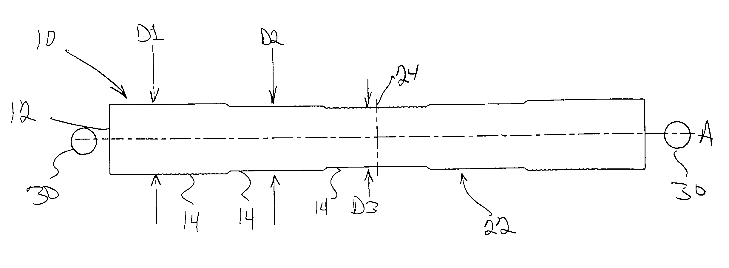
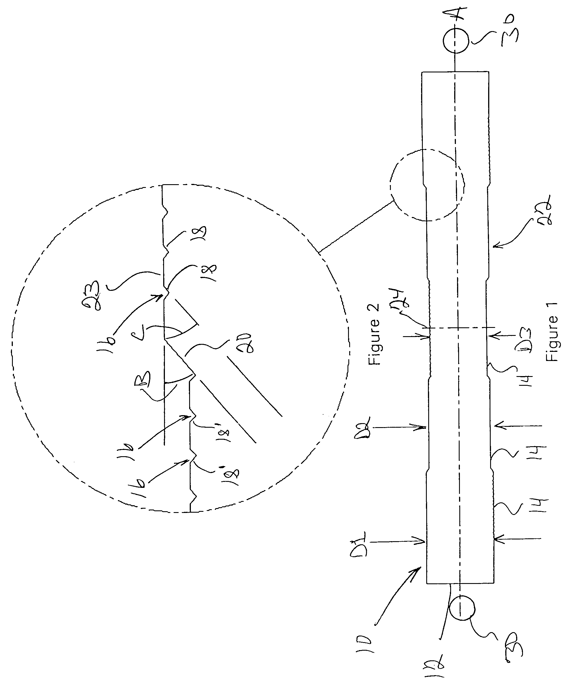
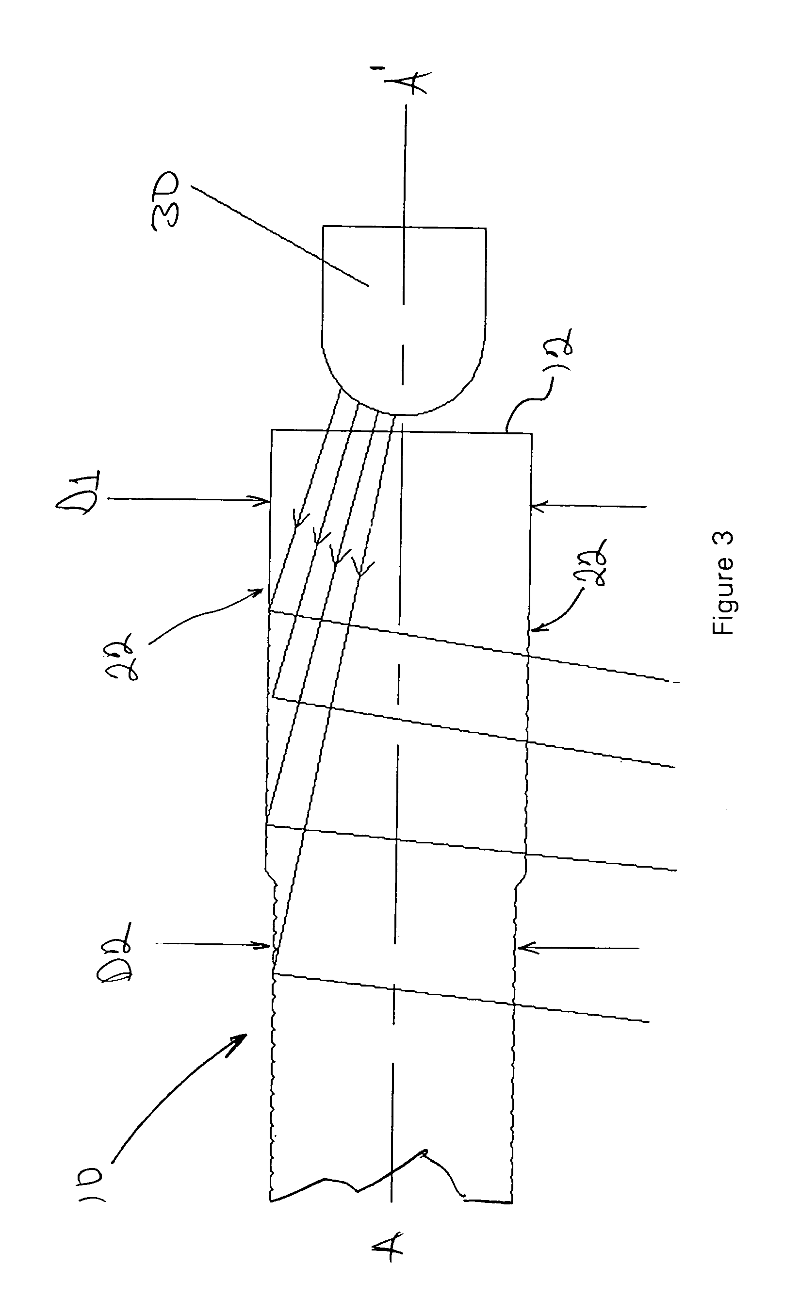
[0014]Exemplary embodiments of an illumination system in accordance with aspects of the present invention will be described with reference to FIGS. 1–4. FIG. 1 illustrates an exemplary light distribution cylinder according to aspects of the present invention. The illustrated light distribution cylinder 10 is a molded solid rod of optical-grade plastic. The exterior surface 22 of the light distribution cylinder 10 is divided into a sequence of progressively smaller diameter cylindrical steps 14. The light distribution cylinder 10 has longitudinal ends 12 at a first diameter D1. As the light distribution cylinder 10 progresses away from each end 12, subsequent steps 14 have smaller diameters D2, D3. The exemplary light distribution cylinder 10 illustrated in FIG. 1 includes a sequence of three steps 14 of progressively smaller diameter from one end 12 to the center 24. The middle step 14 is centered on the center 24 of the cylinder 10.

[0015]The outside surface 23 of each step 14 is in...


PUM


Abstract

An illumination system employs a light distribution cylinder with an exterior surface in the form of a plurality of progressively smaller-diameter cylindrical steps. The outside surface of each cylindrical step is interrupted by V-shaped grooves perpendicular to the axis of the cylinder. Each surface of these V-shaped grooves acts to internally reflect divergent light from a light source positioned at the end of the tube. The light distribution cylinders may be solid or hollow and configured with bilateral symmetry to receive light from either end. The illumination system rearranges divergent directional light from a light source into non-directional light emitted in a cylindrical pattern useful for area illumination.

Description

FIELD OF THE INVENTION[0001]The invention relates to the distribution of light for illumination purposes and more specifically to particular light-transmissive structures configured to redirect and distribute light from one or more directional light sources.BACKGROUND OF THE INVENTION[0002]Optically transmissive components used to transmit and redirect light from point light sources are widely used. Back lit panels for LCD displays are a common example. These mechanisms redirect light from a point light source along the panel by positioning a light source so that its light rays are transmitted in the panel by internal reflection. The light sources typically employed for the back lighting of LCD displays are small light-emitting diodes (LEDs). Recent advances in LED technology have increased the light output and efficiency of these light sources. LEDs are now employed for many directional lighting applications such as reading lamps, flashlights, headlamps, etc. LEDs are point light s...

Claims


Application Information

Patent Timeline
Patent Type & Authority Patents(United States)
IPC IPC(8): F21V7/04F21V7/00F21V8/00
CPCG02B6/001
Inventor LI, YING HUNGPUN, ASHLEY MIN HANGWONG, CHI CHOYCHAN, SIN WINGLOUIE, DEREK CHI HANGLI, LI MAN
Owner WORLD HINT
Why Eureka
Try Eureka