Camera integrated with direct and indirect flash units

a technology of indirect flash and camera, applied in the field of automatic compact cameras, can solve the problems of unfavorable intense direct flash, cumbersome external devices, and photographic professionals continually suffering with finding a solution to diffuse the detrimental effects, and achieve the effects of convenient design, long battery life, and small physical siz

Active Publication Date: 2009-08-20
KHUNTIA ALOK
View PDF17 Cites 50 Cited by
  • Summary
  • Abstract
  • Description
  • Claims
  • Application Information

AI Technical Summary

Benefits of technology

[0014]Power LEDs are comparable in illumination to a xenon flash, yet superior in numerous other facets. The LED is easier to design and is more flexible in its operating mode. The LED is small in physical size, and holds a longer battery charge. Likewise, the drive requirements for power LEDs do not require high peak voltages like xenon tubes require, thus, the LED driver is substantially more compact and requires fewer components of smaller physical size.

Problems solved by technology

Photographers continually suffer with finding a solution to diffusing the detrimental effects caused by harsh direct flash.
Intense direct flash is unfavorable in that the flash light source is a harsh point source of light.
The disadvantage of these two methods is that the cumbersome external devices (the soft box and the umbrella) are required for enhanced lighting and must be set up and manipulated to obtain optimal lighting.
Consequently, much preparation time is required and a user cannot effectively shoot on the go or in casual settings with soft boxes and umbrellas.
Including an indirect flash unit substantially equal in size to existing direct flash units in compact cameras is not practical because the indirect flash would be vastly underpowered for its intended purpose.
Various expensive and ingenious on-camera flash unit attachment alternatives have been proposed, such as a hard hat with a flash mounted thereon, an external flash bracket that mounts the flash higher to push shadows down lower, and / or attaching cumbersome indirect flash units (such as shown and described in U.S. Pat. No. 5,136,312 which is incorporated herein by reference in its entirety) yet none have proposed integrating an adjustable bounce flash unit in a compact manner directly into a camera that can be easily manipulated by a lay consumer.

Method used


Image

  • Camera integrated with direct and indirect flash units
  • Camera integrated with direct and indirect flash units
  • Camera integrated with direct and indirect flash units

Examples


Embodiment Construction

[0026]Particular embodiments of the present invention will now be described in greater detail with reference to the figures. Like reference numerals apply to similar parts throughout the several views.

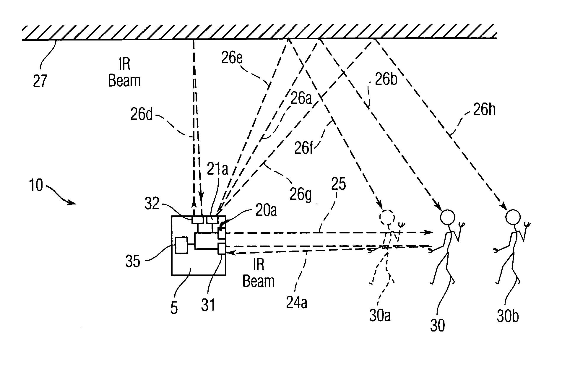
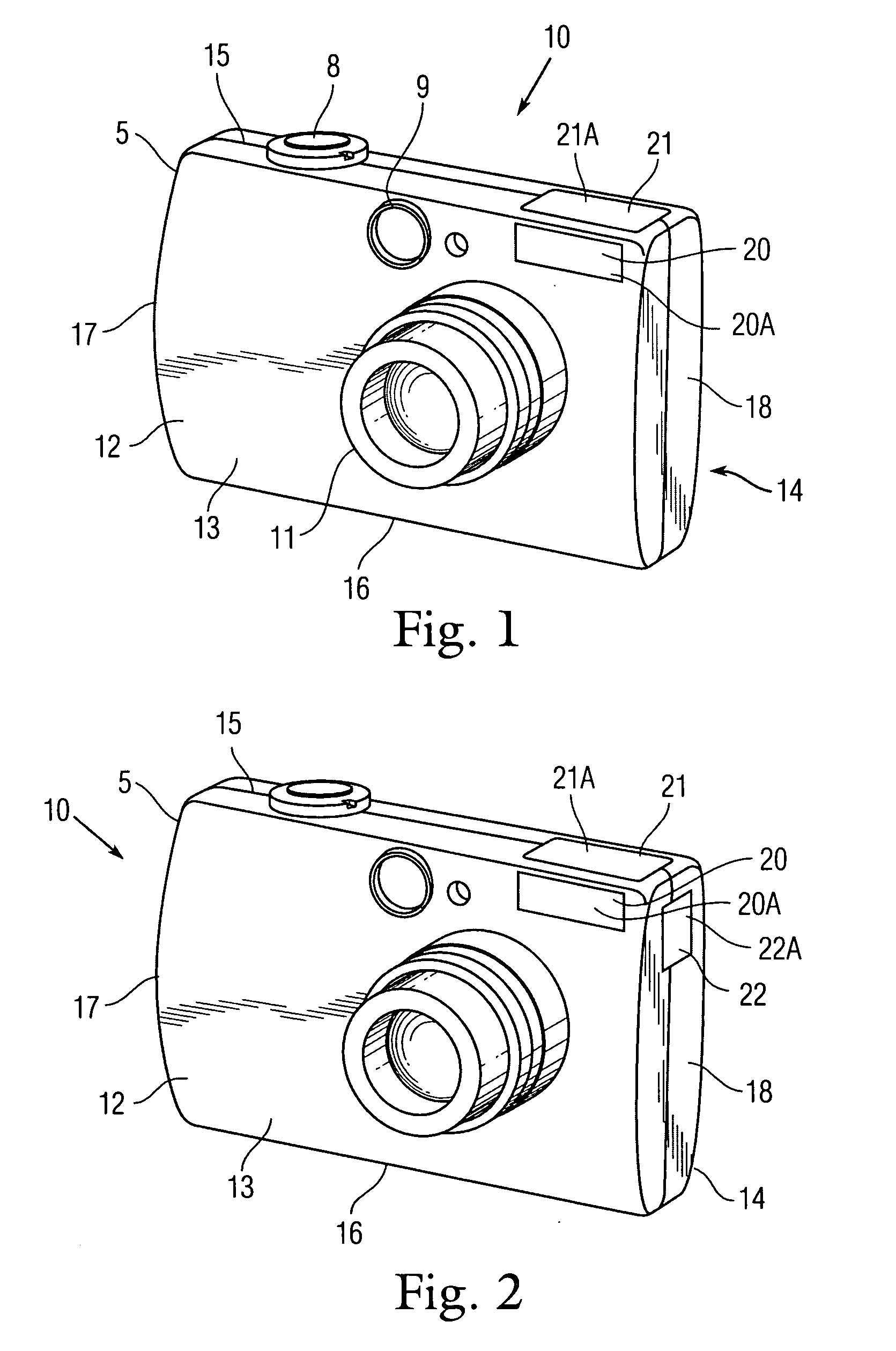
[0027]This invention overcomes the conventional problems described above by providing an automated compact camera such as a point-and-shoot or DSLR including a built-in, indirect, flash unit that provides optimized indirect reflective illumination to the object being photographed. In general, in a first embodiment, the camera will utilize a two-flash system. The camera provides a conventional single direct flash camera and adds at least one set of flash components. The at least one additional sets of flash components would be embodied as an indirect flash unit.

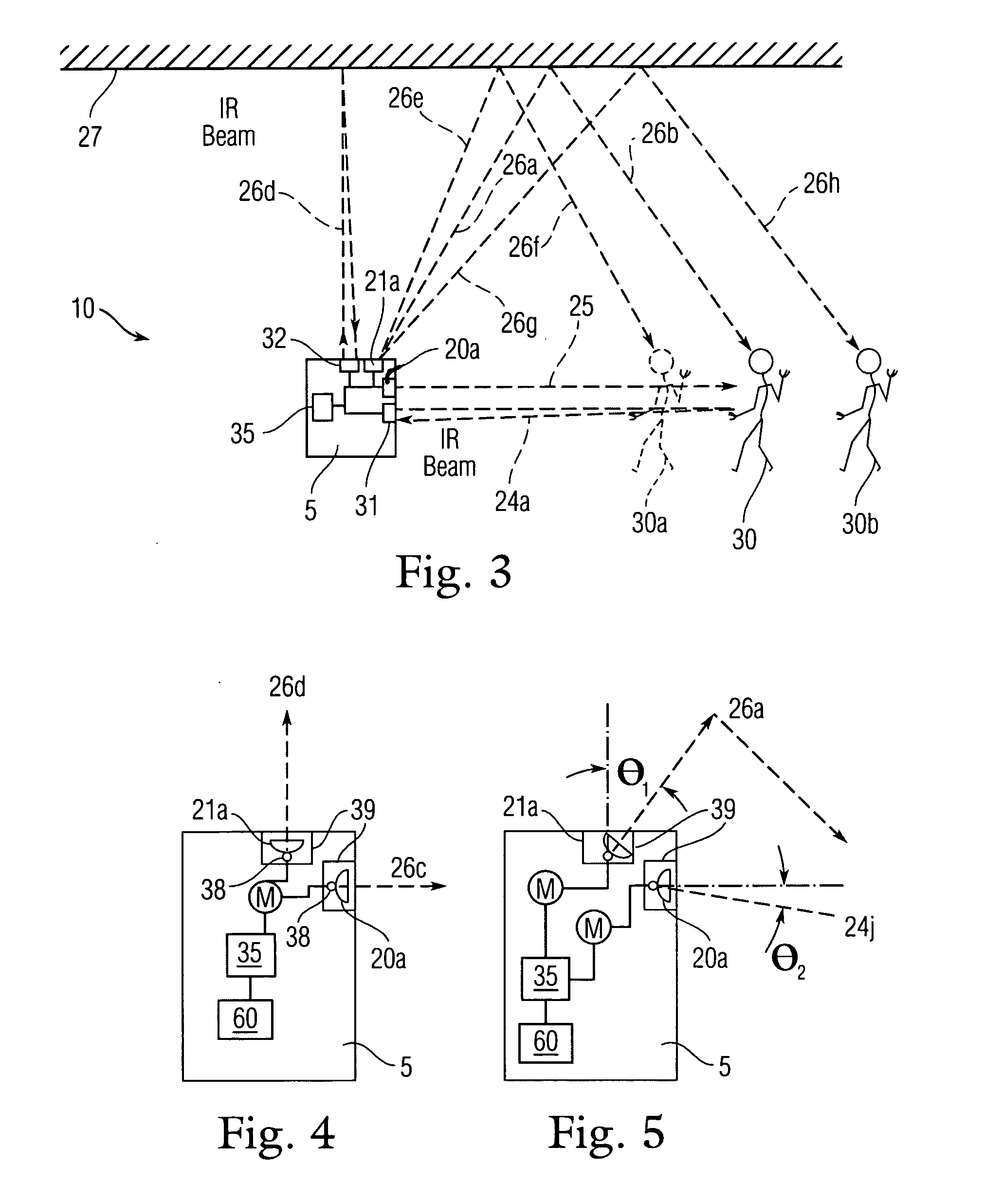
[0028]The indirect flash unit may be pointed in a direction which would cause the projected light to bounce off of a wall, a ceiling or a surface prior to illuminating the object. The direct flash unit would trigger the indirect ...


PUM


Abstract

A compact camera with a compact camera body integrated with a lens, a direct flash module and an indirect flash module. The direct flash unit includes a flash light emission window arranged to project direct illumination in a first direction toward an object to be photographed. The indirect flash unit includes an indirect flash light emission window arranged to project indirect bounce illumination in a second direction off of an indirect reflecting surface to the object. The camera also has a controller that receives a first signal containing information from a first light sensor connected to the direct flash unit, and a second signal containing information from a second light sensor connected to the indirect flash unit. In response to the received first and second signals, the controller selectively adjusts the amount of flash illumination projected from the direct and indirect flash units.

Description

BACKGROUND OF THE INVENTION[0001]1. Field of the Invention[0002]The present invention relates generally to a photography camera that provides direct and indirect flash capabilities, and more particularly to an automated compact camera including a built-in, indirect, flash unit that provides optimized indirect reflective illumination to the object being photographed.[0003]2. Description of the Related Art[0004]Photographers continually suffer with finding a solution to diffusing the detrimental effects caused by harsh direct flash. Intense direct flash is unfavorable in that the flash light source is a harsh point source of light. One skilled in the art of photography understands that “bounce flash,” (i.e., flash aimed away from the object, such as at a light-colored surrounding wall and / or ceiling which is allowed to bounce toward the object) is one solution that will soften the intense illuminating and shadowing effects of direct flash and cast a smoother continuous hue of neutral ...

Claims


Application Information

Patent Timeline
Patent Type & Authority Applications(United States)
IPC IPC(8): G03B15/06
CPCG03B15/06G03B15/02G03B15/05G03B17/18
Inventor KHUNTIA, ALOK
Owner KHUNTIA ALOK
Why Eureka
Try Eureka