Combined container-syringe and assembly method of the same

a container and container technology, applied in the field of combined containers, can solve the problems of inability to perform minor adjustments to align, loss of convenience and safety of the device, and high demand for improvements

Inactive Publication Date: 2005-11-22
ARTE
View PDF10 Cites 79 Cited by
  • Summary
  • Abstract
  • Description
  • Claims
  • Application Information

AI Technical Summary

Benefits of technology

[0010]In consideration of the aforementioned, it is an object of the present invention to provide a method of assembling a combined container-syringe by means of which it is possible to fit an injection needle to a syringe body with the positions of the scale, cutting surface of the injection needle, and finger rest of the finger grip reliably in alignment with each other on the circumference of the syringe body.
[0011]In addition, it is an object of the present invention to also provide a combined container-syringe that is extremely convenient, safe, and easily detachable, wherein the positions on the circumference of the syringe body of the scale, cutting surface of the injection needle, and finger rest of the finger grip are in alignment with each other.
[0032]In addition, in the aforementioned assembly method it is possible to further provide, between said aligning process and said mark display process, a drug filling process of filling the interior of said cylinder with a drug.
[0036]In the aforementioned assembly method it is possible to further provide a process of engaging a transparent or semi-transparent protector, for covering said injection needle, to said cylindrical tip after fitting an injection needle to said cylindrical tip.

Problems solved by technology

Consequently, it is not possible to perform minor adjustments to align the positions of the cutting surface of the injection needle, the finger rest of the finger grip, display scale, and the like with each other.
With this action, the convenience and safety of the device are lost, such that improvements thereof are in great demand.
In particular, when the tip of the syringe body uses the aforementioned luer lock method, it is not possible to determine where to orient and fix the position of the cutting surface of the injection needle, which has been assembled with respect to the relationship between the screw position, tapered portion of the tip (luer tip), and thickness of the injection needle at the needle base.
Likewise, it is also not possible to freely adjust the position of the cutting surface of the injection needle, such that even when the cutting surface is oriented in a different direction than that of the display scale and the like, or alternatively is not aligned with the position of the finger rest of the finger grip (flange or collar), the injection must be inconveniently administered in the aforementioned state.
In addition, there is also the danger that the user will, at times, forget that the tip utilizes a luer lock mechanism, and attempt to forcibly adjust the positions of the cutting surface of the injection needle with the scale of the syringe body, and the like.
At such times, problems exist such as causing damage to the needle base or luer lock tip screw when forcibly rotating the injection needle to adjust the position of the cutting surface of the injection needle with that of the scale of the syringe body, and the like; and loosening of the lock between the injection needle and syringe body during attempts to adjust the cutting surface with the display scale by rotating the injection needle in the direction opposite that of the screw lock, which in turn, results in leakage of the medication from between the aforementioned tip and needle.
In this manner, the preparation of an injection becomes extremely complex.

Method used


Image

  • Combined container-syringe and assembly method of the same
  • Combined container-syringe and assembly method of the same
  • Combined container-syringe and assembly method of the same

Examples


first embodiment

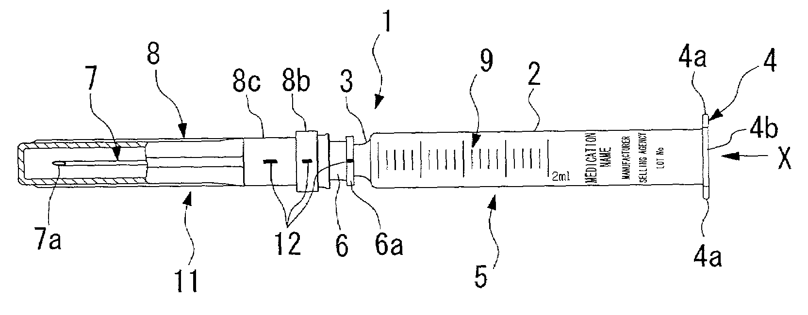
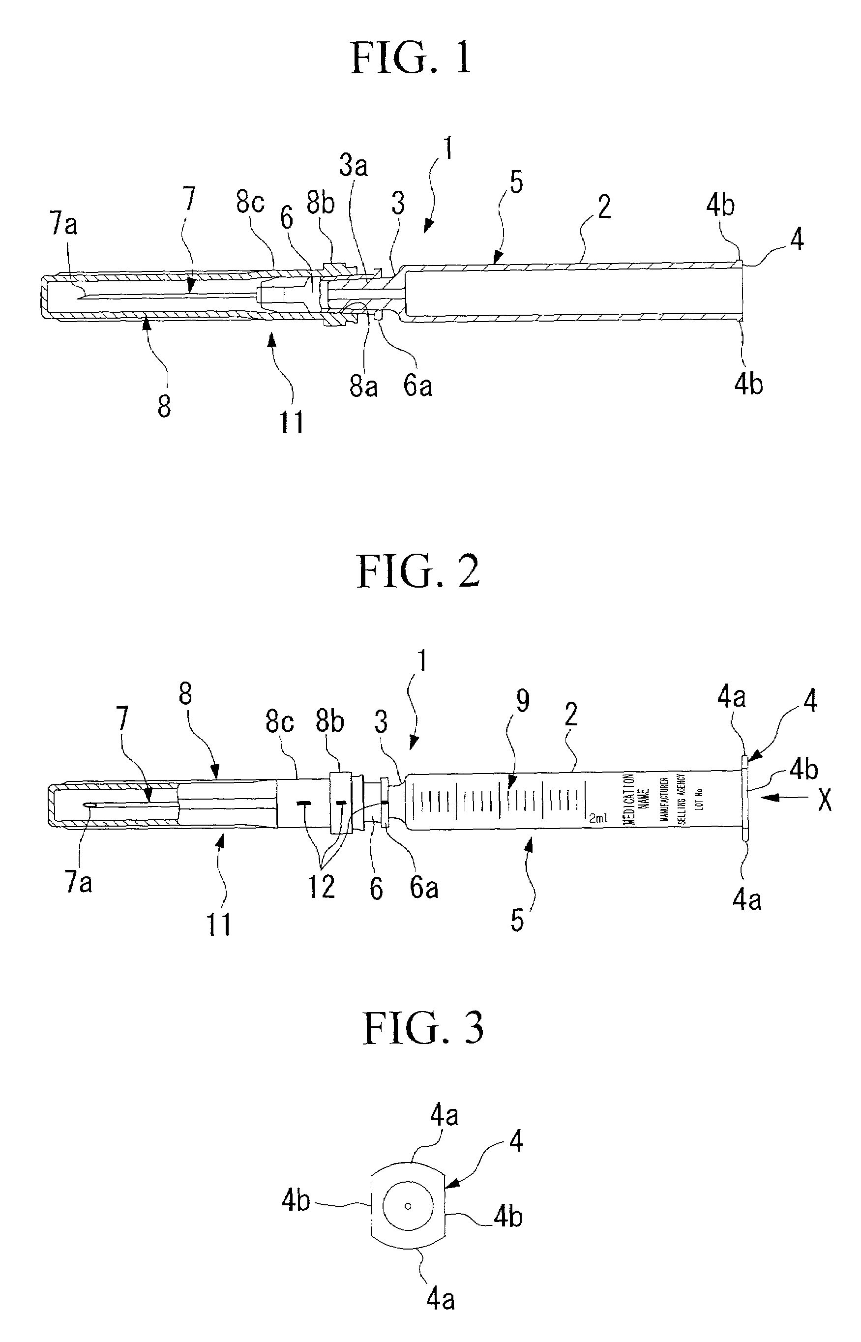
[0072]FIGS. 1 to 3 show a combined container-syringe 1 according to the present invention.

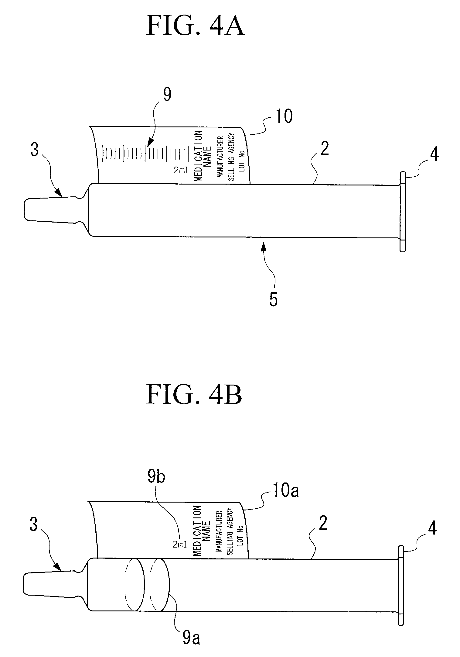
[0073]This combined container-syringe 1 comprises a syringe body 5 comprising a cylindrical-shaped cylinder 2 with a cylindrical tip 3 provided at the anterior end thereof, and a plunger; a finger grip 4 provided at the posterior end of the aforementioned cylinder 2; an injection needle 7 attached to a needle base (attachment) fitted into the aforementioned cylindrical tip 3; and a protector 8, the opening 8a of which engages to the exterior portion of the needle base 6 of the injection needle, and serves to cover the aforementioned injection needle 7. The aforementioned cylindrical tip 3 of the syringe body 5 and finger grip 4 are formed into a single body with the cylinder 2.

[0074]The aforementioned finger grip, as shown in FIG. 3, comprises a pair of finger rests 4a, 4a, and a pair of a smooth surfaces 4b, 4b; the aforementioned smooth surfaces 4b, 4b are each provided at a position that for...

second embodiment

[0080]In the following, a combined container-syringe 1A according to the present invention will be described with reference to FIG. 5.

[0081]This combined container-syringe 1A differs from the aforementioned combined container-syringe 1 in that instead of having the finger grip 4 integrated into a single body with the cylinder 2 as in the combined container-syringe 1 of the aforementioned embodiment, the finger grip 13 is engaged to the cylinder 2 as a separate body, and is engaged in a manner allowing rotation around the axial circumference of the aforementioned cylinder 2. The remaining structures of this combined container-syringe 1A are identical to those of the aforementioned combined container-syringe 1. With regard to the structural components of the aforementioned combined container-syringe 1A, the components that are identical those of the aforementioned combined container-syringe 1 are denoted using the same numeral, and their explanations are omitted.

[0082]The aforemention...

third embodiment

[0085]In the following, a combined container-syringe 1B according to the present invention will be described with reference to FIG. 7.

[0086]This combined container-syringe 1B differs from the aforementioned combined container-syringe 1 in that instead of integrating the aforementioned cylindrical tip 3 into a single body with the cylinder 2 as in the combined container-syringe 1A of the aforementioned second embodiment, a hub luer lock 14 is fitted, as a cylindrical tip, in an attachable manner to the anterior end of the cylinder 2. The aforementioned injection needle assembly 11 is thus fitted to the front end of this hub luer lock 14. The remaining structures of this combined container-syringe 1B are identical to those of the aforementioned combined container-syringe 1A. With regard to the structural components of this combined container-syringe 1B, the components that are identical those of the aforementioned combined container-syringe 1A are denoted using the same numeral, and t...


PUM

PropertyMeasurementUnit
temperaturesaaaaaaaaaa
temperatureaaaaaaaaaa
circumferenceaaaaaaaaaa

Abstract

The present invention provides a combined container-syringe comprising a syringe body containing a cylindrical-shaped cylinder; a cylindrical tip provided at the anterior end of said cylinder; a finger grip fitted to the posterior end of the cylinder; an injection needle fitted to the cylindrical tip; and a protector covering said injection needle. In addition, the present invention provides a method of assembling a combined container-syringe characterized in comprising an injection needle assembly preparatory process of preparing an injection needle assembly; a detection process of detecting the position of the cutting surface; a mark display process of indicating the detected position of the cutting surface; an aligning process of aligning the positions of the mark and a scale display provided on the exterior portion of the cylinder, on the circumference of the cylinder; and a fitting process of fitting the injection needle assembly to the cylindrical tip.

Description

BACKGROUND OF THE INVENTION[0001]1. Field of the Invention[0002]The present invention relates to a combined container-syringe which can be pre-filled with a drug, stored, and immediately used after removal from the packaging at the time of usage, and an assembly method of the same.[0003]2. Description of Related Art[0004]Combined container-syringes, in which an injection needle is pre-fitted to the tip of a syringe body, can be immediately used upon removal from the packaging material without complicated operations. Recently, these combined container-syringes are enjoying wide use in hospital settings due to their superior convenience and ability to reduce the work of physicians and nurses alike.[0005]However, with regard to the conventional combined container-syringe, the injection needle is randomly assembled with respect to the syringe body, such that, in general, the positions on the circumference of the syringe body of the numbers showing the scale and capacity, characters, med...

Claims


Application Information

Patent Timeline
Patent Type & Authority Patents(United States)
IPC IPC(8): A61M5/31A61M5/34A61M5/00A61M5/32
CPCA61M5/3129A61M5/34A61M5/001A61M5/3202A61M5/3287Y10T29/49881A61M2005/3132A61M2005/3139A61M2205/583A61M2207/00
Inventor SHIMAZAKI, SEIJI
Owner ARTE
Why Eureka
Try Eureka