Methods and systems for operating an aerosol generator

a generator and aerosol technology, applied in the field of liquid aerosol generators, can solve the problems of inadvertent installation and nebulization of incorrect drugs into the aerosol generator, the inability to deliver the wrong drugs, and the inability to meet the needs of patients, so as to improve the safety of the patient and increase the efficiency of the delivery of the aerosol to the patien

Inactive Publication Date: 2005-11-29
NOVARTIS FARMA
View PDF63 Cites 85 Cited by
  • Summary
  • Abstract
  • Description
  • Claims
  • Application Information

AI Technical Summary

Benefits of technology

[0014]The present invention provides devices and methods for improving a level of safety to the patient and for providing an increased efficiency of delivery of an aerosol to the patient

Problems solved by technology

While the existing aerosol generators have proven to be effective, the existing aerosol generators suffer some limitations.
One problem with existing aerosol generators is that users may inadvertently install and nebulize an incorrect drug nebule into the aerosol generator.
As can be appreciated, delivery of the wrong drug can be extremely dangerous, if not fatal.
Another problem with existing aerosol generators is that the aerosol generator cannot identify the liquid in the nebule.
Consequently, it has proven to be difficult to provide an efficient delivery of the aerosolized pharmaceutical to the patient.
This is especially in issue with respect to patients that receive some of all of their inspiratory air from a ventilator device.
Existing nebulizers may deliver a constant flow of aerosol into the ventilator tubing, which can lead to a significant amount of aerosol lingering in the tubing or other elements of the overall ventilator system—this lingering aerosol may not be inhaled, as it collects while the patient is exhaling or otherwise not inhaling, resulting in a significant amount of aerosolized medication being pushed out of the system, such as during exhalation, without being inhaled by the patient.
Such situations are problematic for a number or reasons.
First, the dosage of drug that actually is inhaled by the patient may be significantly inaccurate because the amount of medication the patient actually receives into the patient's respiratory system may vary with fluctuations of the patient's breathing pattern.
Further, a significant amount of drug that is aerosolized may end up being wasted, and certain medications are quite costly, thus health-care costs can be escalated.
This can end up medicating individuals in the patient's surroundings and this may give rise to adverse effects with respect to such individuals.
Moreover, in a hospital environment such individuals may be either health-care providers, who could be exposed to such air pollution over a prolonged period of time, or other patients, who may be in a weakened condition or otherwise overly sensitive to exposure to non-prescribed or excessive amounts of a medication.

Method used


Image

  • Methods and systems for operating an aerosol generator
  • Methods and systems for operating an aerosol generator
  • Methods and systems for operating an aerosol generator

Examples


Embodiment Construction

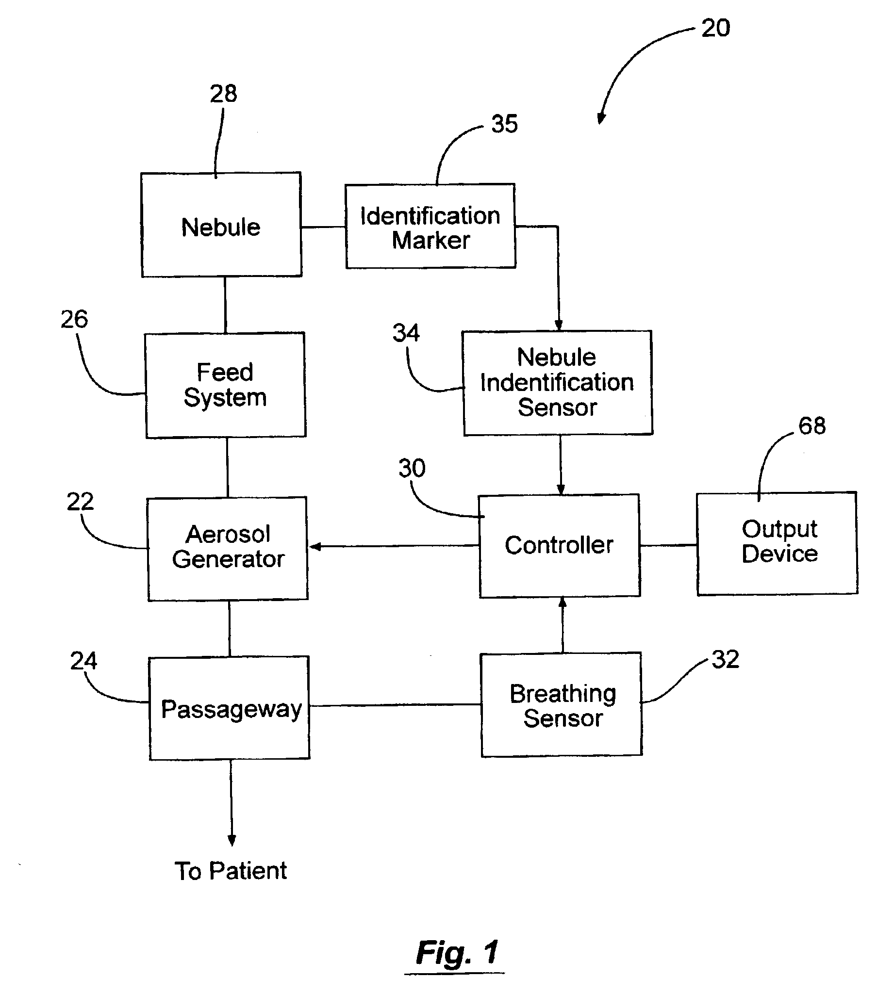
[0049]The aerosol generator systems of the present invention, in one aspect, include an aerosol generator coupled to a controller that is in communication with at least one sensor such that delivery sequence of the aerosol to the patient can be based at least in part on the information obtained with the sensors. In some exemplary embodiments, the system includes a nebule identification sensor to read an identification marker on the nebule so as to identify the type of liquid that is disposed within the nebule. In other exemplary embodiments, the system includes a breathing characteristic sensor that monitors and records the breathing characteristics of the patient so as to allow the controller to direct the delivery of the aerosol to coincide with the patient's breathing pattern. In yet other exemplary embodiments, the aerosol generator system includes both a nebule identification sensor and a breathing characteristic sensor.

[0050]FIG. 1 schematically illustrates an exemplary aeroso...


PUM

PropertyMeasurementUnit
wall thicknessaaaaaaaaaa
timeaaaaaaaaaa
particle size distributionaaaaaaaaaa

Abstract

A nebule comprising at least one identification marker or label can be coupled an aerosol generator. The identification marker can be sensed by a sensing device on the aerosol generator so as to identify the liquid in the nebule to the controller of the aerosol generator. The controller of the aerosol generator can control the aerosol generator based on the information read from the identification marker.

Description

CROSS-REFERENCES TO RELATED APPLICATIONS[0001]The present application is related to U.S. patent application Nos. 09 / 876,542, filed Jun. 7, 2001, now abandoned, 09 / 876,402, filed Jun. 7, 2001, now abandoned, and 09 / 812,987, filed Mar. 20, 2001, the complete disclosures of which are incorporated herein by reference.[0002]The present application is a continuation-in-part of U.S. patent application Ser. No. 09 / 849,194, filed May 4, 2001, now U.S. Pat. No. 6,615,824 which claims the benefit of Ireland patent application No. PCT / IE / 00051, filed May 5, 2000, which are incorporated herein in their entirety.[0003]The present application is a continuation-in-part of U.S. patent application Ser. No. 09 / 812,755 filed Mar.20, 2001, which is incorporated herein in its entirety.[0004]The present application is a continuation-in-part and claims the benefit of U.S. Provisional Application No. 60 / 349,763, filed Jan. 15, 2002, which is incorporated herein in its entirety.[0005]The present application ...

Claims


Application Information

Patent Timeline
Patent Type & Authority Patents(United States)
IPC IPC(8): A61J1/06A61K47/04A61M15/00A61M16/00A61K9/12A61M16/04A61M16/06A61M16/08B05B15/00B05B17/06B65D1/09
CPCA61J1/065A61M15/00A61M15/0028A61M15/0085A61M16/08B05B17/0646B65D1/095A61M15/0031A61M15/0033A61J2205/10A61J2205/60A61M16/00A61M16/04A61M16/06A61M2016/0021A61M2016/0024A61M2205/52A61M2205/6045A61M2205/6054A61M2205/6072A61M2205/8206A61M2205/8262A61M2209/082B65D2203/00A61M16/024
Inventor SMITH, NIALLPOWER, JOHNFINK, JAMES B.KLIMOWICZ, MICHAEL
Owner NOVARTIS FARMA
Why Eureka
Try Eureka