Metal terminal with weakened part
a metal terminal and weakened part technology, applied in the direction of coupling contact members, multi-conductor cable end pieces, coupling device connections, etc., can solve the problems of troublesome disassembly and great deal of work
- Summary
- Abstract
- Description
- Claims
- Application Information
AI Technical Summary
Benefits of technology
Problems solved by technology
Method used
Image
Examples
first embodiment
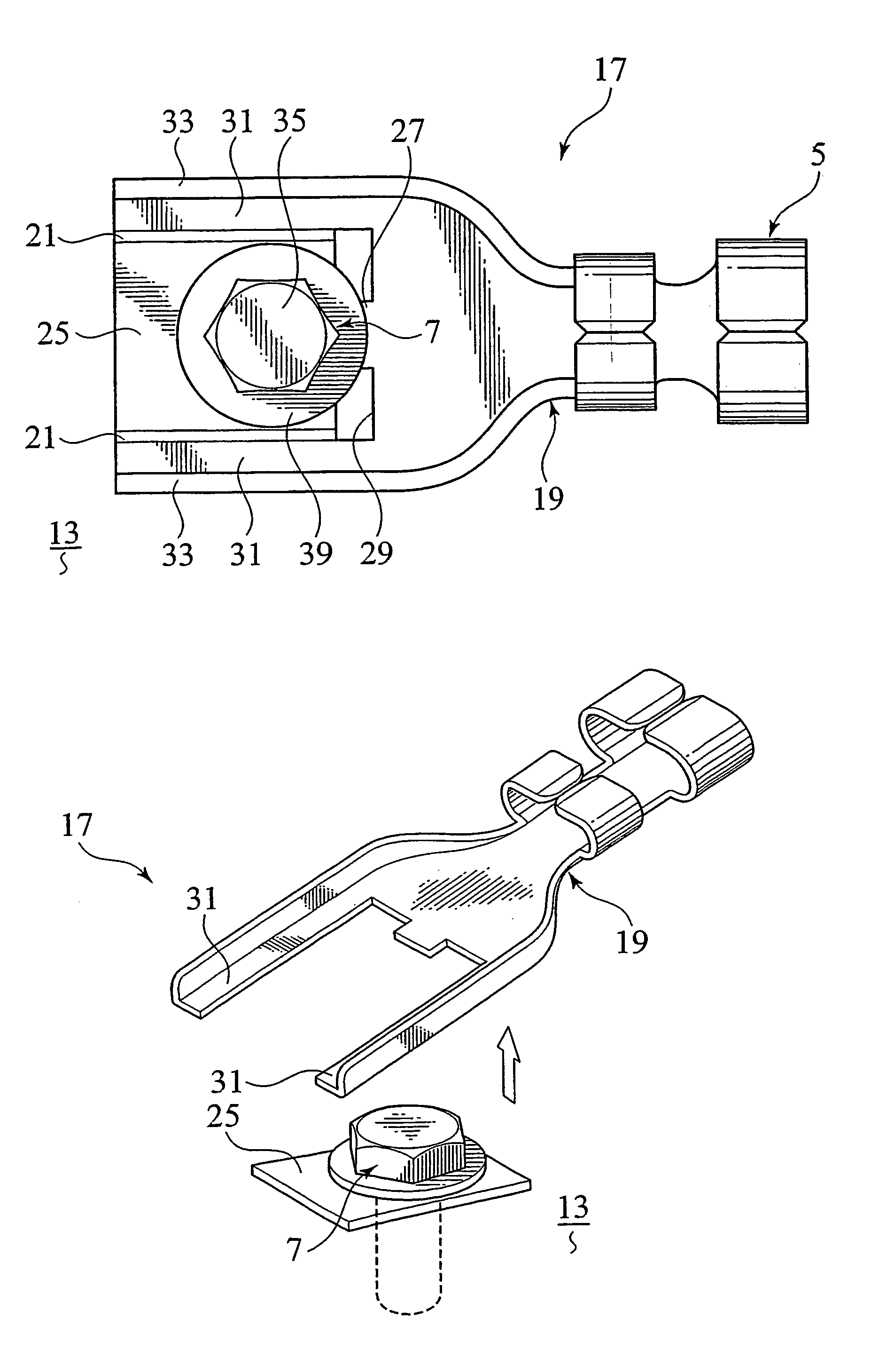
[0075]FIG. 4 is a perspective view of a metal terminal in accordance with the present invention. FIG. 5 is a perspective view showing a condition that the metal terminal of FIG. 4 is fixed to the vehicle body. FIG. 6 is a plan view of the metal terminal of FIG. 5.
[0076]In these figures, reference numeral 17 designates a metal terminal (fittings) of this embodiment. The metal terminal 17 has a plate-shaped terminal body 19 having a crimp part 5 which is crimped to a not-shown wire and a fastening part 25 connected to the terminal body 19 through breakable weakened parts 21, 21 and having a through-hole 23 for passage of a bolt 7 as a fastening member. Noted that the above weakened parts 21, 21 will be referred to “breaking parts” hereinafter. The terminal body 19 is provided with a co-fastening part 27 of which tip side is fastened by the bolt 7, together with the fastening part 25.
[0077]The terminal body 19 is made from an elongated metal plate. Again, the terminal body 19 is shaped...
second embodiment
[0136]Various changes and modifications may be made to the present invention. For example, although the breaking parts 45, 45 are partially curved on their respective base sides in the shown embodiment, the breaking parts 45, 45 may be partially curved on their tip sides. Alternatively, they may be partially curved at their intermediate portions between the tip sides and the base sides.
[0137][3rd. Embodiment]
[0138]FIGS. 12 to 14 show the third embodiment of the present invention. In these figures, elements identical to those of the above embodiments are indicated with the same reference numerals respectively and their detailed descriptions are eliminated. FIG. 12 is a perspective view of the metal terminal of the third embodiment. FIG. 13 is a cross-sectional view taken along line XIII—XIII of the breaking part of the metal terminal of FIG. 12. FIG. 14 is a cross-sectional view taken along line XIV—XIV of the breaking part of the metal terminal of FIG. 12.
[0139]As shown in FIGS. 12 ...
third embodiment
[0150]Similarly to the previously-mentioned embodiments, various changes and modifications may be made to the present invention. For example, although the thick-wall parts 59, 59 are respectively arranged on the sides of the leading ends of the projecting parts 58, 58, each of the thick-wall parts 59, 59 may be formed at an intermediate position of the breaking part 57. Additionally, although each breaking part 57 is formed so as to gradually increase its plate thickness in the shown embodiment, the breaking part 57 may be provided with a step part instead of the thick-wall part 59.
[0151]Further, although each of the thick-wall parts 59, 59 has a plate thickness equal to the plate thickness of the terminal body 60 and the fastening part 61 in the shown embodiment, the same part 59 has a plate thickness smaller than the plate thickness of the terminal body 60 and the fastening part 61.
[0152]The above-mentioned embodiment is also applicable to a metal terminal for connection of a plur...
PUM
 Abstract
Description
Claims
Application Information
 - R&D
- Intellectual Property
- Life Sciences
- Materials
- Tech Scout
- Unparalleled Data Quality
- Higher Quality Content
- 60% Fewer Hallucinations
Browse by: Latest US Patents, China's latest patents, Technical Efficacy Thesaurus, Application Domain, Technology Topic, Popular Technical Reports.
© 2025 PatSnap. All rights reserved.Legal|Privacy policy|Modern Slavery Act Transparency Statement|Sitemap|About US| Contact US: help@patsnap.com


