Metal terminal with weakened part

a metal terminal and weakened part technology, applied in the direction of coupling contact members, multi-conductor cable end pieces, coupling device connections, etc., can solve the problems of troublesome disassembly and great deal of work

Inactive Publication Date: 2005-01-06
YAZAKI CORP
View PDF6 Cites 17 Cited by
  • Summary
  • Abstract
  • Description
  • Claims
  • Application Information

AI Technical Summary

Benefits of technology

[0009] Under the circumstances, it is therefore an object of the present invention to provide a metal terminal which is

Problems solved by technology

Therefore, the metal terminals 1, 2 mentioned above have a problem of taking a great deal of

Method used


Image

  • Metal terminal with weakened part
  • Metal terminal with weakened part
  • Metal terminal with weakened part

Examples


first embodiment

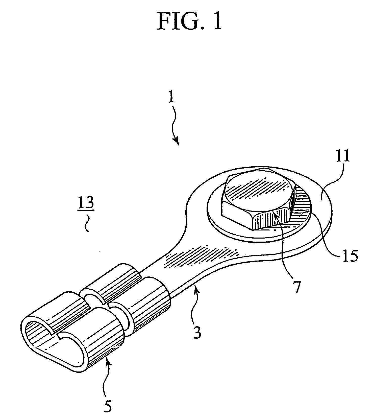
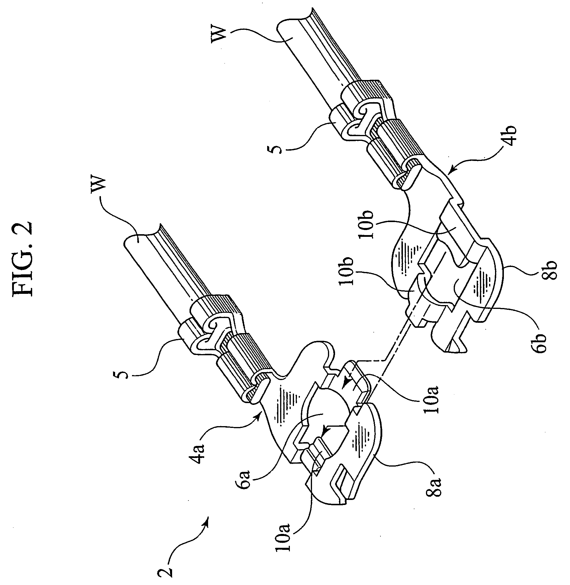
[0075]FIG. 4 is a perspective view of a metal terminal in accordance with the present invention. FIG. 5 is a perspective view showing a condition that the metal terminal of FIG. 4 is fixed to the vehicle body. FIG. 6 is a plan view of the metal terminal of FIG. 5.

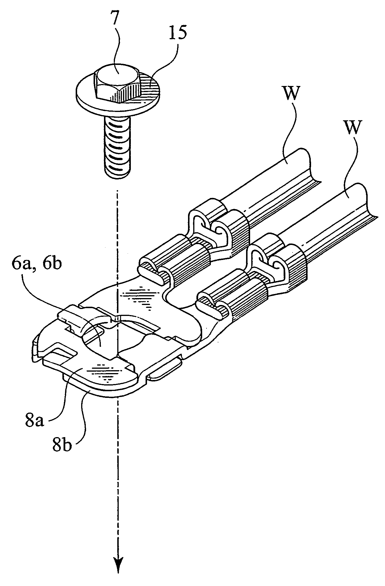
[0076] In these figures, reference numeral 17 designates a metal terminal (fittings) of this embodiment. The metal terminal 17 has a plate-shaped terminal body 19 having a crimp part 5 which is crimped to a not-shown wire and a fastening part 25 connected to the terminal body 19 through breakable weakened parts 21, 21 and having a through-hole 23 for passage of a bolt 7 as a fastening member. Noted that the above weakened parts 21, 21 will be referred to “breaking parts” hereinafter. The terminal body 19 is provided with a co-fastening part 27 of which tip side is fastened by the bolt 7, together with the fastening part 25.

[0077] The terminal body 19 is made from an elongated metal plate. Again, the terminal body 19 is sha...

second embodiment

[0136] Various changes and modifications may be made to the present invention. For example, although the breaking parts 45, 45 are partially curved on their respective base sides in the shown embodiment, the breaking parts 45, 45 may be partially curved on their tip sides. Alternatively, they may be partially curved at their intermediate portions between the tip sides and the base sides.

[0137] [3rd. Embodiment]

[0138] FIGS. 12 to 14 show the third embodiment of the present invention. In these figures, elements identical to those of the above embodiments are indicated with the same reference numerals respectively and their detailed descriptions are eliminated. FIG. 12 is a perspective view of the metal terminal of the third embodiment. FIG. 13 is a cross-sectional view taken along line XIII-XIII of the breaking part of the metal terminal of FIG. 12. FIG. 14 is a cross-sectional view taken along line XIV-XIV of the breaking part of the metal terminal of FIG. 12.

[0139] As shown in FIGS...

third embodiment

[0150] Similarly to the previously-mentioned embodiments, various changes and modifications may be made to the present invention. For example, although the thick-wall parts 59, 59 are respectively arranged on the sides of the leading ends of the projecting parts 58, 58, each of the thick-wall parts 59, 59 may be formed at an intermediate position of the breaking part 57. Additionally, although each breaking part 57 is formed so as to gradually increase its plate thickness in the shown embodiment, the breaking part 57 may be provided with a step part instead of the thick-wall part 59.

[0151] Further, although each of the thick-wall parts 59, 59 has a plate thickness equal to the plate thickness of the terminal body 60 and the fastening part 61 in the shown embodiment, the same part 59 has a plate thickness smaller than the plate thickness of the terminal body 60 and the fastening part 61.

[0152] The above-mentioned embodiment is also applicable to a metal terminal for connection of a ...


PUM


Abstract

A metal terminal has a terminal body (19) having a crimp part (5) crimped to a wire and a fastening part (25) connected to the terminal body (19) through breaking parts (21, 21). The fastening part (25) has a through-hole (23) for passage of a bolt (7). The metal terminal further includes a co-fastening part (27) formed in the terminal body (19). The tip side of the co-fastening part (27) is fastened to a vehicle body (13) by the bolt (7), together with the fastening part (25). When detaching terminal body (19) from the vehicle body (13), one side of the one terminal body (19) is pulled up in a direction opposite to the fastening direction of the bolt (7) under condition that the fastening part (25) and the co-fastening part (27) are together fastened by the bolt (7). Consequently, the co-fastening part (27) is released from its fastened condition and a breaking force is applied on the breaking parts (21, 21).

Description

TECHNICAL FIELD [0001] The present invention relates to a metal terminal, alias, metal fittings attached to a vehicle by means of a fastening member while the metal terminal is connected with an end of a wire. BACKGROUND ART [0002]FIG. 1 shows a proposed metal terminal 1. The metal terminal 1 includes a plate-shaped terminal body 3 provided, on one side in the longitudinal direction, with a crimp part 5 which is crimped to a not-shown wire. On the other side of the terminal body 3, it has a fastening part 11 having a through-hole (not shown) formed to let a bolt 7 as the fastening member pass. [0003] When using the metal terminal 1, the crimp part 5 is firstly crimped to the wire's end having its insulating cover peeled and thereafter, the fastening part 11 is fastened to a vehicle body 13 by means of the bolt 7. In fastening the part 11 to the vehicle body 13, the bolt 7 is inserted into the above through-hole of the part 11 while interposing a washer 15 between the bolt 7 and the ...

Claims


Application Information

Patent Timeline
IPC IPC(8): H01R4/38H01R11/11H01R11/12H01R11/26
CPCH01R11/12Y10S439/907H01R11/26
Inventor ONO, SHUJIARAI, HIROAKIGOTO, HIROKITAKAMATSU, MASAHIRONOMURA, KOJITAKEUCHI, SHYUNSAKUITO, KEIICHITSUKAMOTO, YOSHIHIDEWAKUI, MASANORIYONEYAMA, ISAO
Owner YAZAKI CORP
Why Eureka
Try Eureka