Vehicle seat weight sensor

a weight sensor and vehicle seat technology, applied in the direction of instruments, pedestrian/occupant safety arrangements, force/torque/work measurement apparatus, etc., can solve the problems of uniform weight reading, injuring the occupants, and inability to detect the weight of the front passenger seat, so as to achieve reliable and cost-effective effects

Inactive Publication Date: 2005-11-29
CTS CORP ELKHART
View PDF71 Cites 79 Cited by
  • Summary
  • Abstract
  • Description
  • Claims
  • Application Information

AI Technical Summary

Benefits of technology

[0008]It is a feature of the invention to provide a reliable and cost-effective vehicle seat weight sensor for detecting the weight of a seat occupant. The sensor uses strain sensitive resistors.
[0009]An additional feature of the invention is to provide a weight sensor for sensing the weight of an occupant in a vehicle seat. The seat has a seat pan and a seat member. The weight sensor includes a case mounted between the seat pan and the seat member. One or more strain gauge resistors are mounted in the case. The resistors generate an electrical signal in response to the case being stressed by the weight of the seat occupant. The electrical signal changes as a function of the weight of the occupant. A fastener passes through the seat member, the case, and the seat pan. The fastener secures the sensor between the seat pan and the seat member. The case is adapted to transfer to the strain gage resistor the weight of the occupant up to a first magnitude. The case prevents the strain gage from receiving weight beyond that of the first magnitude.

Problems solved by technology

In some situations, these safety devices can injure the occupants.
For example, an occupant in the front passenger seat may be injured by deployment of an airbag, if the occupant is a baby or child.
One problem encountered in measuring the weight of a seat occupant is that the weight reading needs to be uniform when the vehicle is moving.
The load cells of the prior art have suffered from giving false readings when subjected to side loads.
Prior art seat weight sensors have suffered from requiring an extensive redesign of the seat frame in order to be installed.

Method used


Image

  • Vehicle seat weight sensor
  • Vehicle seat weight sensor
  • Vehicle seat weight sensor

Examples


2nd alternative embodiment

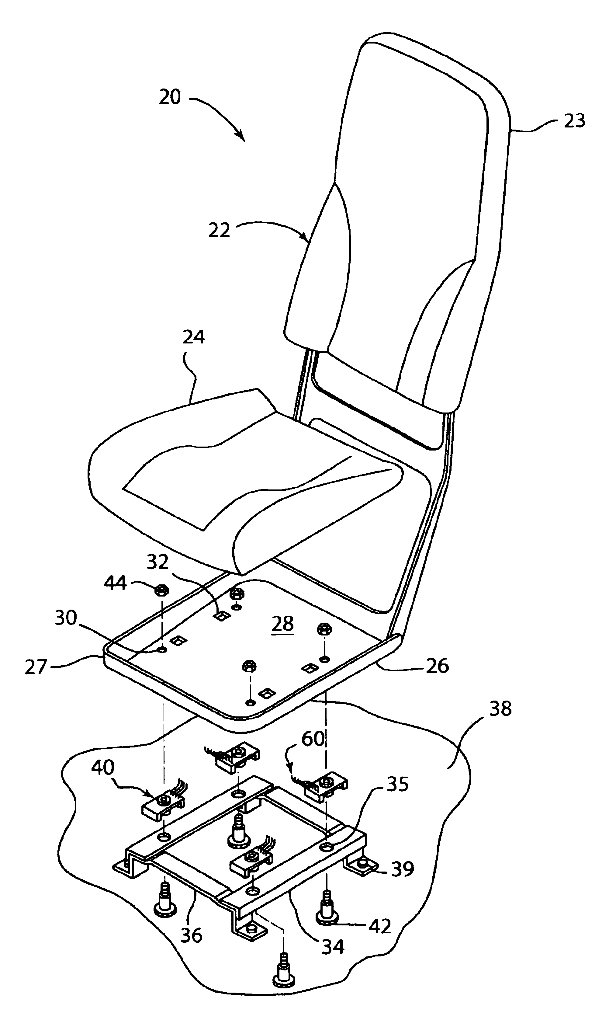
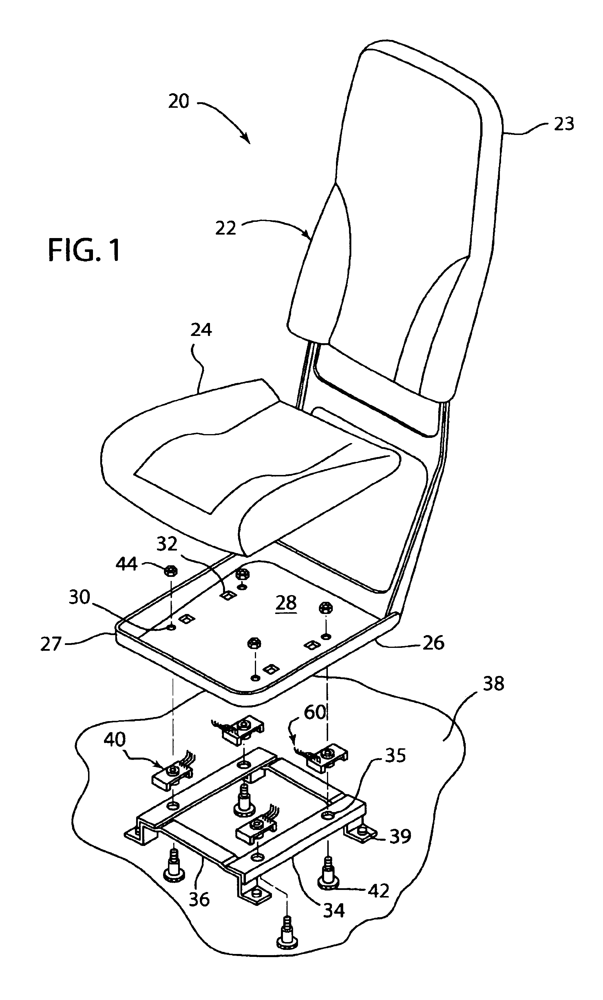
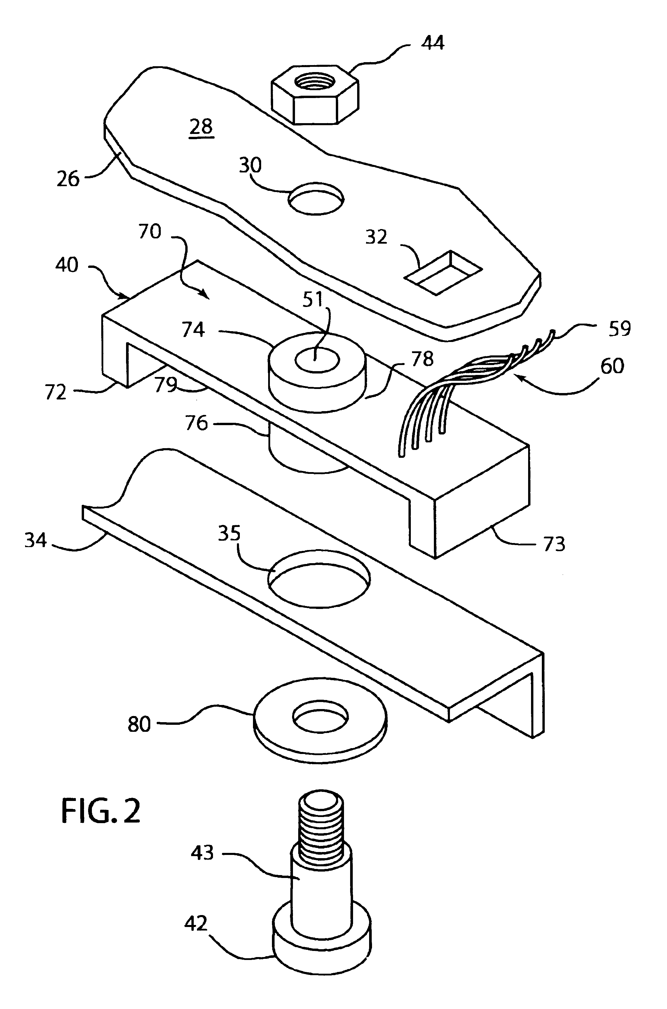
[0046]Referring to FIG. 9, details of an alternative weight sensor assembly 100 are shown. The location of sensor 100 is different than in previous embodiments. Sensor 100 is located above seat pan 26. In some seat configurations, it may be desirable to have the sensor located above the seat pan in order to reduce the overall height of the seat assembly. Seat pan 26 has openings 102 through which blades 72 and 73 extend to contact seat member 34. Fastener 42 has a boss 104 that fits into hole 35.

[0047]First spring washer 90 is retained between plate 108 and upper boss 74. Spring washer 90 is compressed during assembly by nut 44 pushing plate 108 downwardly. Spring washer 90 is compressed to a load L1 of approximately 100 kilograms of spring force. Elastomeric washer 80 is compressed between boss 104 and seat pan 26. A second spring washer 106 is located between fastener 42 and seat member 34. Spring washer 106 is compressed during assembly by nut 44 pulling on fastener 42. Spring wa...


PUM

PropertyMeasurementUnit
weightaaaaaaaaaa
tensionaaaaaaaaaa
spring forceaaaaaaaaaa

Abstract

A seat weight sensor for detecting the weight of a seat occupant. The weight sensor has a case mounted between a seat pan and a seat member. One or more strain gauge resistors are mounted in the case. The resistors generate an electrical signal in response to the case being stressed by the weight of the seat occupant. The electrical signal changes as a function of the weight of the occupant. A fastener passes through the seat member, the case, and the seat pan. The fastener secures the sensor between the seat pan and the seat member. The case is adapted to transfer to the strain gage resistor the weight of the occupant up to pre-determined level. The case prevents the strain gage from receiving weight beyond that of the pre-determined level such that the sensor is not damaged by an excessive load. The case also allows the weight sensor to be insensitive to off-axis forces that might otherwise contribute to inaccurate weight readings.

Description

BACKGROUND OF THE INVENTION[0001]1. Field of the Invention[0002]This invention relates to an automobile weight sensor for detecting the presence of a person in a car seat, and in particular to a sensor that can detect the presence of an occupant using strain sensitive resistors and provide an electrical signal to control activation of an airbag.[0003]2. Description of the Related Art[0004]Automobiles are equipped with restraint systems, such as seat belts, and inflatable restraint systems, such as airbags, to improve passenger safety. In some situations, these safety devices can injure the occupants. For example, an occupant in the front passenger seat may be injured by deployment of an airbag, if the occupant is a baby or child. It is desirable to control the operation of the airbag according to the weight of a passenger for improved performance of seat belts and airbags. A device for measuring the weight of a passenger sitting on a vehicle seat is needed to prevent or modify the d...

Claims


Application Information

Patent Timeline
Patent Type & Authority Patents(United States)
IPC IPC(8): B60N2/00B60R21/01B60R21/015G01G19/414H01C10/10
CPCB60N2/002G01G19/4142H01C10/10B60R21/01516B60R21/0152
Inventor RAINEY, ROBERT R.
Owner CTS CORP ELKHART
Why Eureka
Try Eureka