Direct Drive MWD Tool

Inactive Publication Date: 2010-02-04
THE GEARHART
View PDF14 Cites 24 Cited by
  • Summary
  • Abstract
  • Description
  • Claims
  • Application Information

AI Technical Summary

Benefits of technology

[0029]The principal advantage of the present invention is that it provides a much more compact, cost effective, and reliable MWD tool that is strongly resistant to clogging with LCM. Another advantage of the present invention is that it provides a tool that, if the electrical power supply, electronics, or motor fail, the tool will mechanically return to a retracted position, so as to prevent restriction of drilling fluid so that drilling operations can continue. Another advantage of the present invention is that it provides a tool that permits addition of a second MWD tool above it as a reserve tool.
[0030]A principal advantage of the present invention is that it provides a more compact and effective pressure compensation system. Another advantage of the present invention is that it provides segregation

Problems solved by technology

A principal disadvantage of existing MWD tools is the susceptibility of pilot valves to clogging due to lost circulation material (LCM).
The LCM becomes trapped between the pilot valve and the seat of the valve, causing the tool to fail.
Even when complete failure is averted, the magnetic couplings may begin to slip in the high torque condition created by the interfering LCM, and thus rendering false pulse patterns.
When an MWD tool fails from pilot valve clogging with LCM, drilling fluid is unable to pass though the tool.
The result is that even if the operator elected to forgo the measurements provided by the tool, he cannot drill ahead, as there is insufficient fluid flow rate passing through the tool to the drill bit.
Another disadvantage of the combined lubrication and pressure compensation system of known MWD tools is reliability and serviceability.
The seal against the rotating shaft will have a limited life.
The brushes and field coils of the motor will eventually pick-up the metal-iron fines and impurities in the oil, causing the motor to fail.
Conventional MWD tools with lengthy components and integrated lubrication and compensation reservoirs are not, thus, serviceable in the field.
Another disa

Method used


Image

  • Direct Drive MWD Tool
  • Direct Drive MWD Tool
  • Direct Drive MWD Tool

Examples


Embodiment Construction

[0043]The following description is presented to enable any person skilled in the art to make and use the invention, and is provided in the context of a particular application and its requirements. Various modifications to the disclosed embodiments will be readily apparent to those skilled in the art, and the general principles defined herein may be applied to other embodiments and applications without departing from the spirit and scope of the present invention. Thus, the present invention is not intended to be limited to the embodiments shown, but is to be accorded the widest scope consistent with the principles and features disclosed herein.

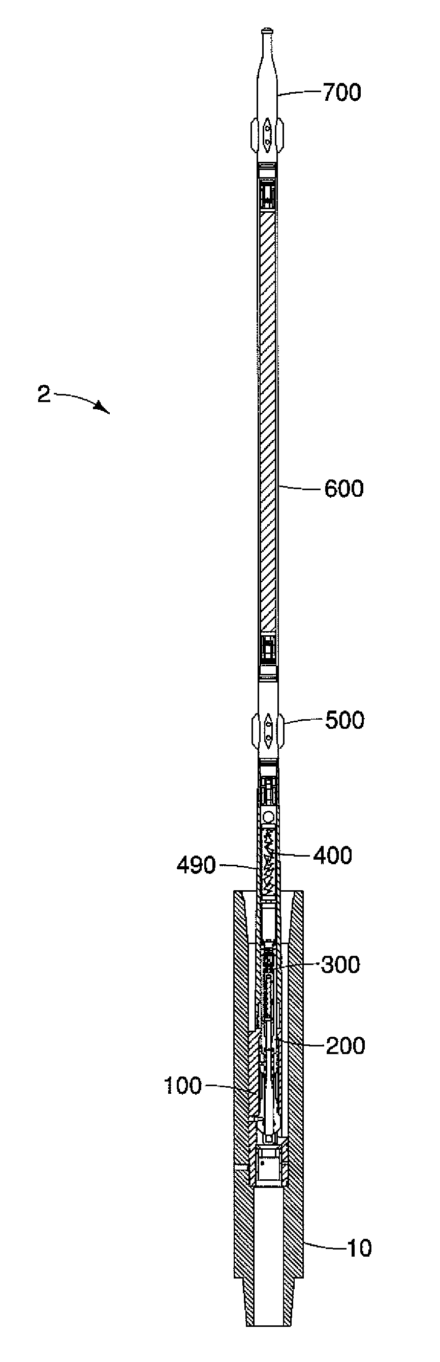
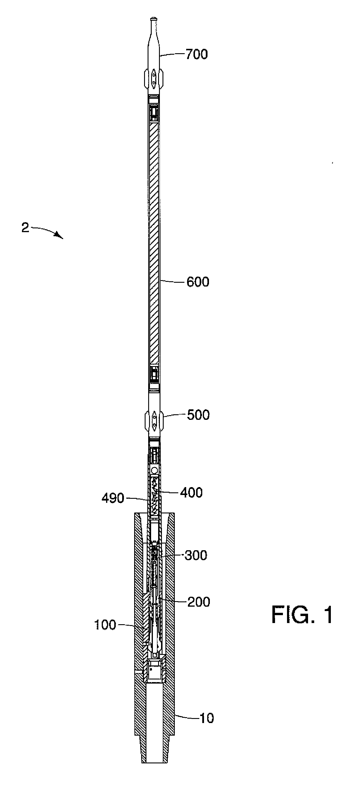
[0044]FIG. 1 is a partially sectioned side view of MWD tool 2, illustrating MWD tool 2 engaged in a landing sub 10. MWD tool 2 has an upper end and a lower end, the lower end being disposed closest to the drill bit. A lower housing 100 comprises the lower end. A pulser 200 is located in lower housing 100. Pulser 200 includes a pressure balance ...


PUM


Abstract

The present invention relates to a measurement-while-drilling tool [2] with a mechanically driven poppet [216] which eliminates the flow of drilling fluid through the tool, and reliance on surface supplied hydraulic force to activate the poppet [216]. The present invention eliminates the pilot valve system, and generates a fluid pulse from a direct drive relationship between a reversible motor [414], actuator [300], and poppet valve [216]. A pulser [200] has a push rod [214] slidably located inside. Poppet [216] is located on the push rod [214]. Actuator [300] is connected to the pulser [200], and has a ball screw [334] mechanically connected [330] to the push rod [214]. An electric motor [414] and gear train is operatively connected [338] [340] [342] to the ball screw [334]. Motor [414] generates linear movement of the poppet [216] in relation to an orifice [112] to restrict flow and generate a pulse.

Description

TECHNICAL FIELD OF THE INVENTION[0001]The present invention relates to a measurement-while-drilling tool with a direct drive poppet. The tool eliminates the flow of drilling fluid through the tool, and eliminates reliance on surface supplied hydraulic force to activate the main poppet. The present invention eliminates the pilot valve system, and generates a fluid pulse from a direct drive relationship between a reversible motor, actuator, and poppet valve. The simplified and compartmentalized tool vastly increases reliability in formations where lost circulation material is required. The tool design facilitates rapid field servicing and component replacement without the need to remove the tool from the drilling site for specialized service. In particular, the pressure compensation system and reservoir are segregated from fluid integration with the actuator mechanism's lubricants. The present invention provides MWD stacking. The present invention also permits disconnection of tool se...

Claims


Application Information

Patent Timeline
IPC IPC(8): E21B21/08
CPCE21B47/18
Inventor GEARHART, MARVINMILLIGAN, DANIEL E.SMITH, HOWARDNAYLOR, DENNIS L.REDMOND, MICHAEL
Owner THE GEARHART
Why Eureka
Try Eureka