Distributed optical fiber vibration sensing method and apparatus thereof

A distributed optical fiber and vibration sensing technology, applied in the field of sensing, can solve the problems of sensing and monitoring distance limitations, achieve high real-time performance, wide response bandwidth, and expand the application range

Active Publication Date: 2006-11-15
武汉光谷光联网科技有限公司
View PDF1 Cites 51 Cited by
  • Summary
  • Abstract
  • Description
  • Claims
  • Application Information

AI Technical Summary

Problems solved by technology

At the same time, the sensor

Method used


Image

  • Distributed optical fiber vibration sensing method and apparatus thereof
  • Distributed optical fiber vibration sensing method and apparatus thereof
  • Distributed optical fiber vibration sensing method and apparatus thereof

Examples


Example Embodiment

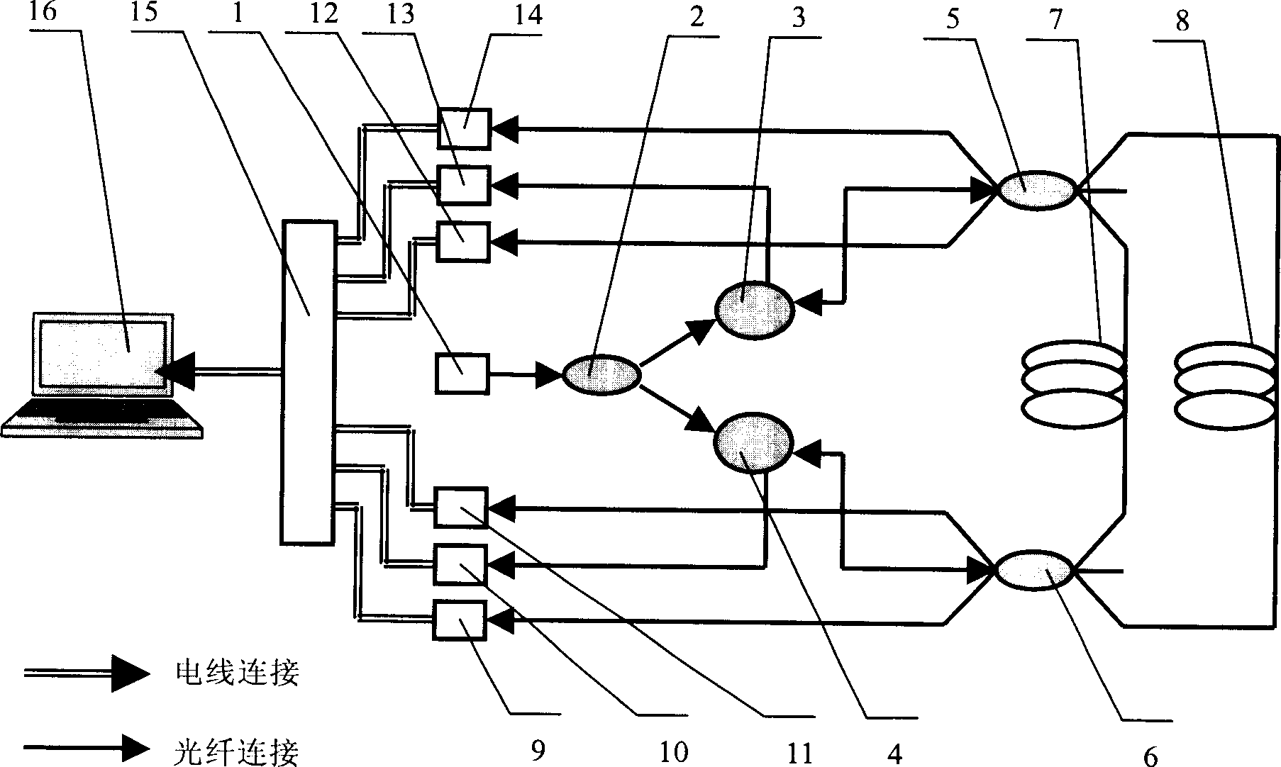
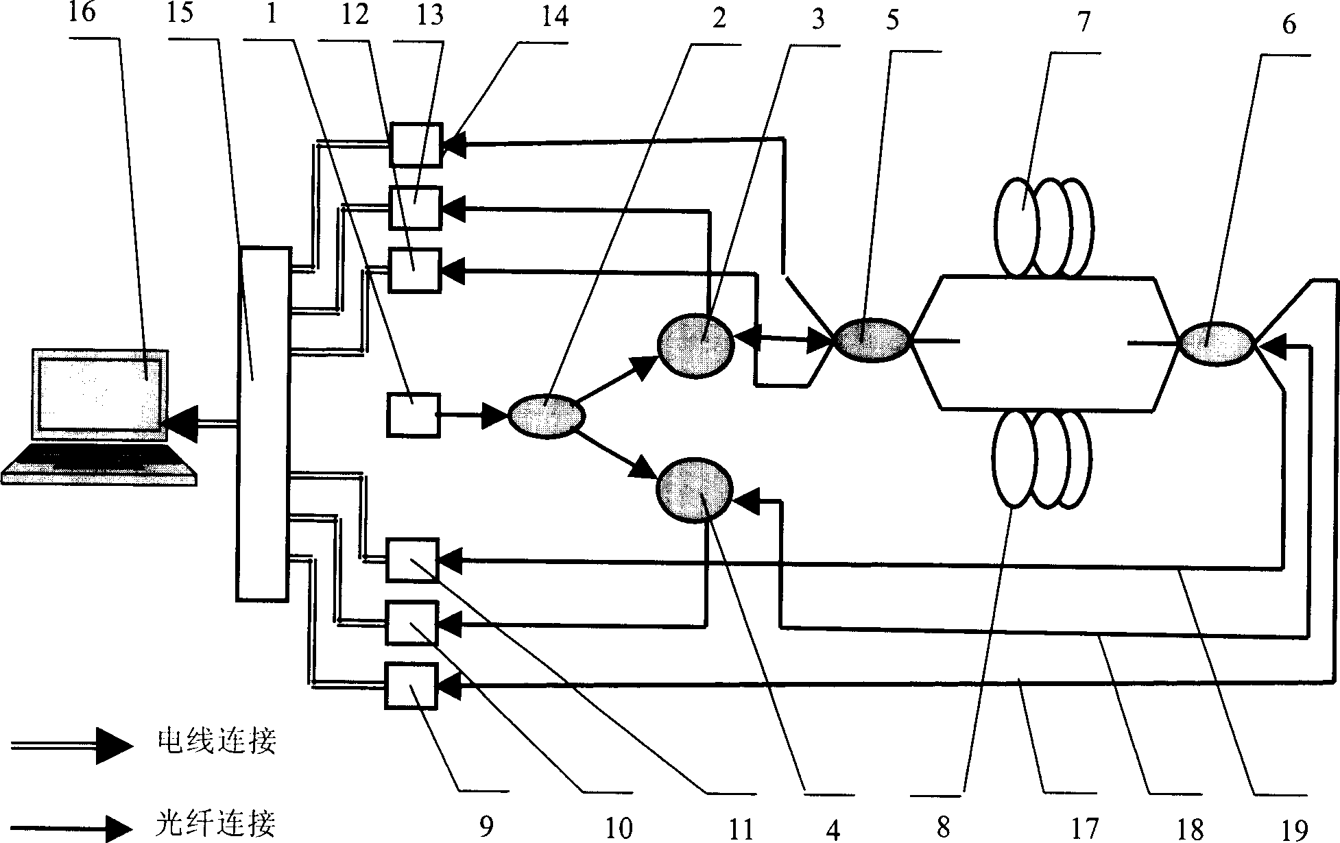
[0022] The invention provides a distributed optical fiber vibration sensing method and device based on a double-ring Mach-Zehnder interferometer.

[0023] 1. Distributed optical fiber vibration sensing method based on double loop Mach-Zehnder interference

[0024] 1. This method includes the following steps:

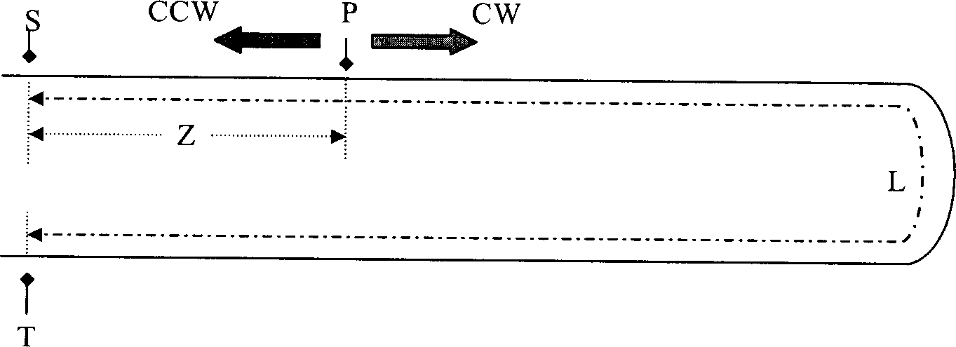
[0025] The laser 1 emits a DC monochromatic light wave, which is coupled into two optical circulators 3 and 4 through a 2×2 fiber coupler 2, and then is coupled in forward and reverse directions through two 3×3 fiber couplers 5 and 6 respectively. Two sensing fibers 7, 8, in which: the light waves propagating in the forward direction converge at the fiber coupler 6 to generate a forward loop Mach-Zehnder interference optical signal, and the light waves propagating in the reverse direction converge at the fiber coupler 5 Generate a reverse loop Mach-Zehnder interference light signal. When the external vibration signal is disturbed along the optical fiber, it will cause the ph...


PUM


Abstract

The present invention relates to a distributed optical fibre vibration sensing method based on double loop Mach-Zehnder interference and its equipment. Said equipment includes the following several portions: laser, fiber-optic coupler, two sensing optical fibres, optical circulator and photoelectric detector. Besides, said invention also provides the concrete steps for implementing the invented distributed optical fibre vibration sensing method.

Description

technical field [0001] The invention relates to the field of sensing technology, in particular to an online real-time monitoring, positioning method and monitoring device for vibration signals of regional perimeters and linear boundaries, which is a distributed optical fiber vibration sensing method based on double-loop Mach-Zehnder interference and device. Background technique [0002] Sensing and alarming systems such as perimeter security, border prevention, earthquake monitoring, and tsunami early warning play a huge role in ensuring the stability of people's lives and protecting people's lives and property. The essence of such systems lies in the detection and analysis of vibration signals . With the development of optical devices and optical communications, fiber optic sensing technology is increasingly used in the field of sensing, gradually replacing some traditional electrical sensors. Due to the essential characteristics of optical fiber are sensitive to signals ...

Claims


Application Information

Patent Timeline
IPC IPC(8): G01H9/00G02B6/26G02B6/42
Inventor 刘德明孙琪真刘海荣袁军国
Owner 武汉光谷光联网科技有限公司
Why Eureka
Try Eureka