Bridgeless boost converter with pfc circuit

A technology of control circuit and single-cycle control, which is applied in the direction of control/regulation system, output power conversion device, DC power input conversion to DC power output, etc., can solve problems such as impractical realization, and achieve total cost reduction and elimination Intrinsic loss, effect of reducing power loss

Inactive Publication Date: 2006-11-15
INTERNATIONAL RECTIFIER COEP
View PDF4 Cites 61 Cited by
  • Summary
  • Abstract
  • Description
  • Claims
  • Application Information

AI Technical Summary

Problems solved by technology

The drawback of this circuit is the reverse recovery of the high-side switch, which would make it impractical to implement

Method used


Image

  • Bridgeless boost converter with pfc circuit
  • Bridgeless boost converter with pfc circuit
  • Bridgeless boost converter with pfc circuit

Examples


Embodiment Construction

[0048] I. Recommended circuit

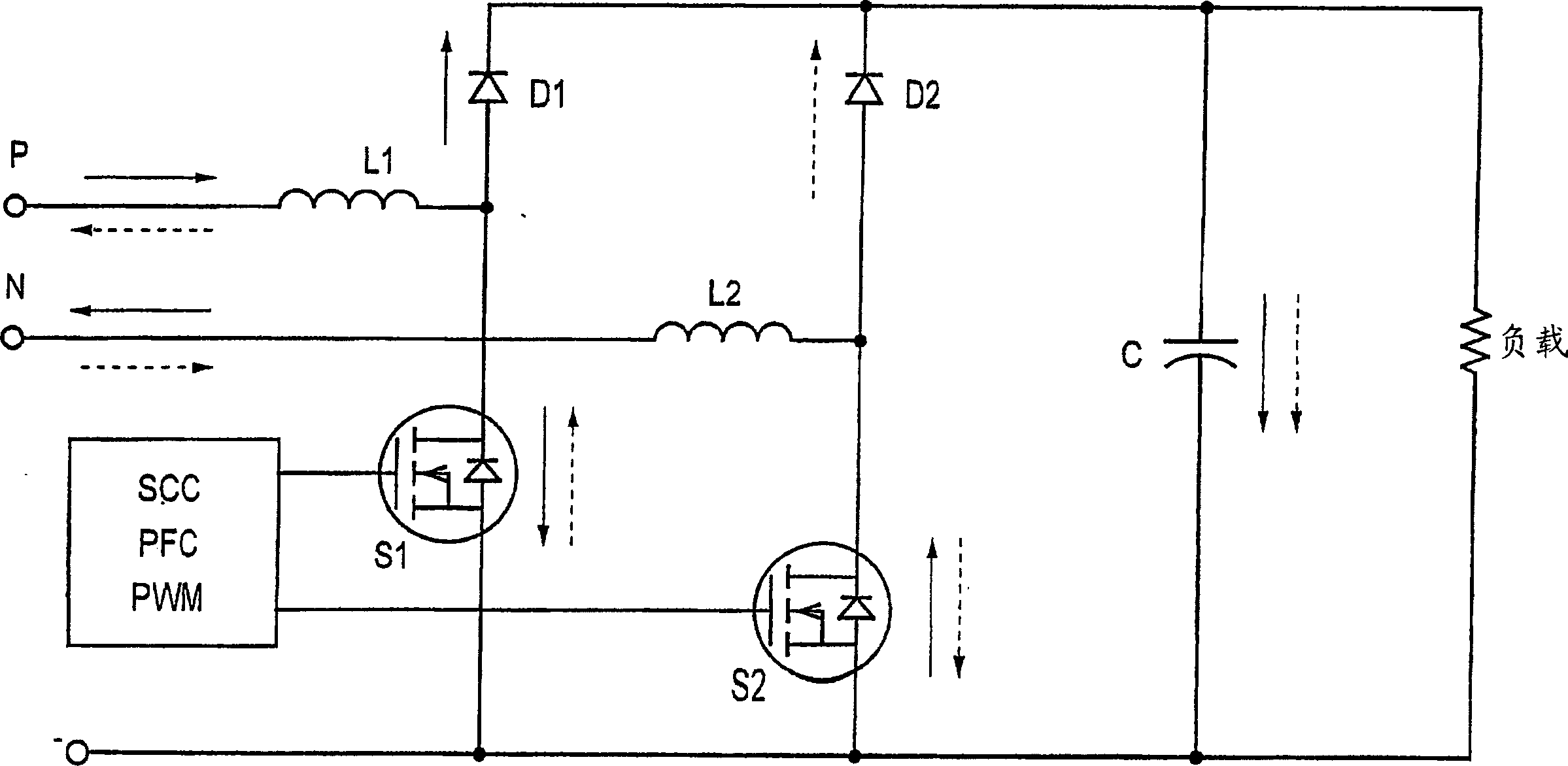
[0049] The proposed circuit does not use the input bridge at all, but replaces the function of the input bridge with two boost diodes and two boost switches. The two boost switches are controlled by a closed loop using One Cycle Control (OCC) a / k / a Single Cycle Control (SCC) techniques.

[0050] The boost inductor in the existing circuit is moved in front of where it performs the rectifier function, and it can be a single inductor, or it can be split into two inductors (as shown), one on each of the two input lines .

[0051] figure 2A simplified circuit diagram is shown in . The circuit consists of two boost inductors L1 and L2 working in parallel. There may be a common core (not shown). Only one inductor can be actively active (boosted) at a time. During the positive portion of the input sine wave (indicated by the solid arrow), the gate of MOSFET S1 is driven high and current flows through the boost inductor L1, thereby charging the in...


PUM


Abstract

The bridgeless boost topology reduces the power dissipation, cost, and size of prior PFC systems by eliminating the intrinsic loss of the input rectifier bridge. Sensing of the input line voltage by the controller is unnecessary. The use of One Cycle Control (also known as Single Cycle Control) allows the Power Factor Correction function to be performed without complex rectification networks to obtain the AC line voltage reference. The use of bi-directional switches makes it possible to control inrush current (the startup over-current due to the charging of the output bulk capacitor), which allows elimination of over-current limiting devices and reduction of the diode surge capability requirements. Moving the boost inductor to the system input adds an additional filtering function, reducing the cost of input EMI filtering.

Description

[0001] Cross References to Related Applications [0002] This application is based on and claims priority from US Provisional Application No. 60 / 507,901, filed October 1, 2003, which is incorporated herein by reference. technical field [0003] The invention relates to a bridgeless boost (BLB) power factor correction circuit structure, in particular to a circuit controlled by a single cycle and / or including a bidirectional switch. Background technique [0004] Power factor correction is required by international standards (EN61000-3-2) to reduce harmonic emissions in AC power systems. [0005] The most common solution, as shown in Figure 1, usually uses an input rectifier bridge consisting of four diodes of appropriate voltage rating connected to a boost switching converter with a voltage loop and a current loop control. The external voltage loop through diode DV tends to keep the output voltage approximately constant. The inner current loop (indicated by the arrow) throu...

Claims


Application Information

Patent Timeline
Patent Type & Authority Applications(China)
IPC IPC(8): H02M3/335
CPCH02M1/0085
Inventor 马尔科·索尔达诺
Owner INTERNATIONAL RECTIFIER COEP
Why Eureka
Try Eureka