Acoustic matching layer and ultrasonic transducer

a technology of ultrasonic transducers and matching layers, which is applied in the direction of liquid/fluent solid measurement, generators/motors, instruments, etc., can solve the problems of insufficient t3%, difficult to make an acoustic matching layer with even lower acoustic impedance of epoxy resin with glass balloons, and difficult to uniformly mix glass balloons and epoxy resin agents. to achieve the effect of minimizing the variation in property

Inactive Publication Date: 2005-11-29
PANASONIC CORP
View PDF9 Cites 15 Cited by
  • Summary
  • Abstract
  • Description
  • Claims
  • Application Information

AI Technical Summary

Benefits of technology

[0056]An ultrasonic transducer fabricating method according to a second aspect of the present invention is a method for fabricating an ultrasonic transducer that includes a piezoelectric layer and an acoustic matching layer provided on the piezoelectric layer. The process of forming the acoustic matching layer includes the steps of: (a) preparing a gel material solution; (b) providing a thickness regulating member having a predetermined height on a surface on which the acoustic matching layer will be defined; (c) feeding the gel material solution onto the surface; (d) substantially equalizing the thickness of a liquid layer, defined by the gel material solution that has been fed onto the surface, with the height of the thickness regulating member; (e) solidifying the gel material solution into a wet gel; and (f) drying the wet gel with a solvent removed therefrom, thereby obtaining the dry gel. In the ultrasonic transducer fabricating method according to the second aspect, the thickness of the acoustic matching layer is controlled at a predetermined thickness, thus minimizing the variation in property, which is usually caused by a variation in the thickness.

Problems solved by technology

However, if the mixture ratio of the glass balloons is increased, then the epoxy resin agent with those glass balloons will have an increased viscosity, thus making it hard to mix the glass balloons and the epoxy resin agent together uniformly.
Consequently, it is difficult to make an acoustic matching layer with even lower acoustic impedance of the epoxy resin with glass balloons.
Even so, when the ultrasonic energy transmittance T is calculated by the Equation (3) described above on such an acoustic matching layer made of the epoxy resin with glass balloons, it can be seen that T≈3%, which is not sufficient.
Thus, the medium easily becomes non-uniform due to the damage of the glass spheres under excessive pressures, separation of the glass spheres under insufficient pressures or foaming of the peeled molten material.
As a result, a variation in characteristic is created in the same acoustic matching layer and the precision of the equipment also varies unintentionally.
Thus, the acoustic matching layer may have a thickness that is significantly different from its preferred value, non-uniform thicknesses, or surface unevenness.
As a result, the performance of the resultant ultrasonic transducer was not good enough.

Method used


Image

  • Acoustic matching layer and ultrasonic transducer
  • Acoustic matching layer and ultrasonic transducer
  • Acoustic matching layer and ultrasonic transducer

Examples


embodiment 1

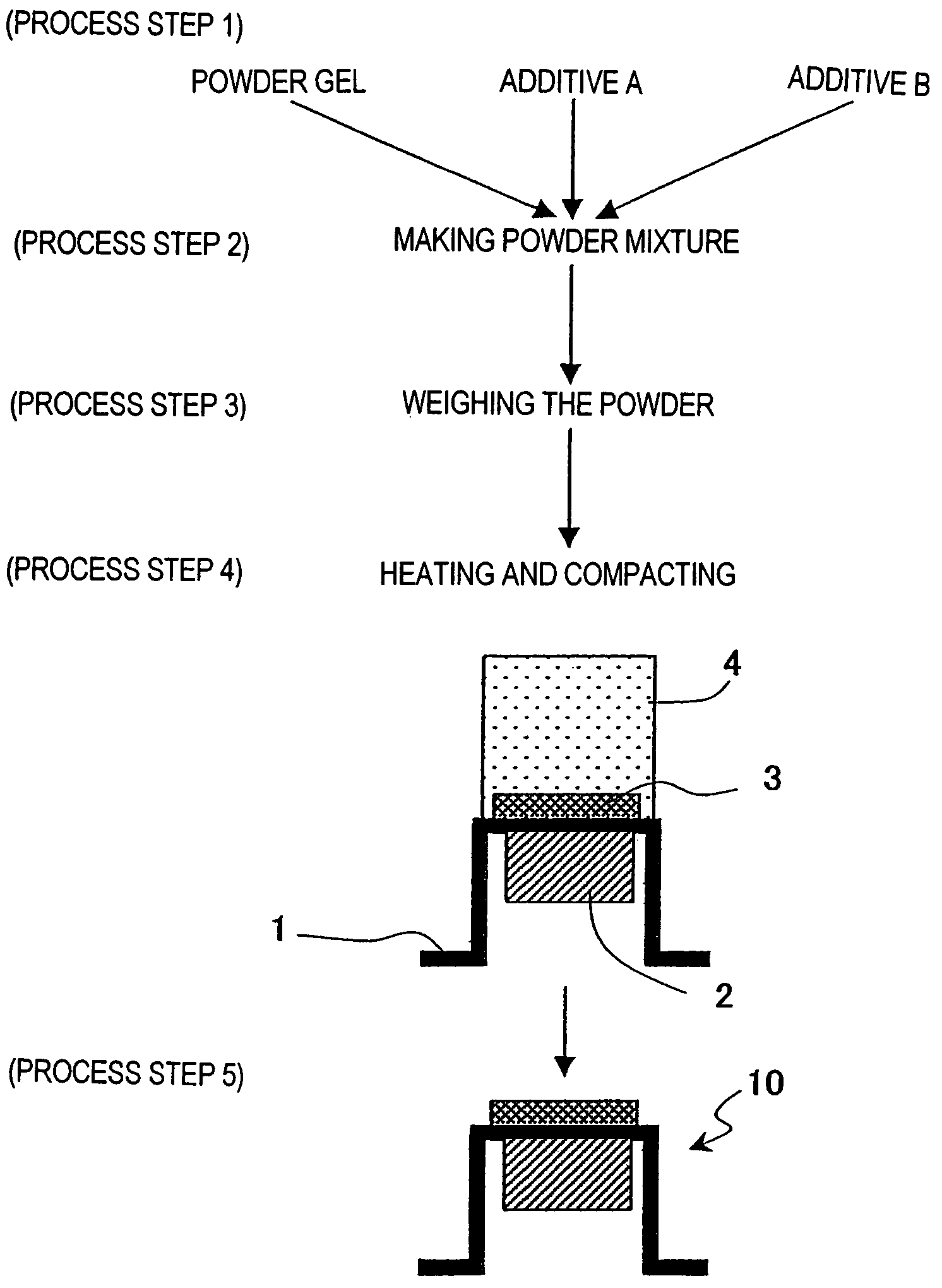
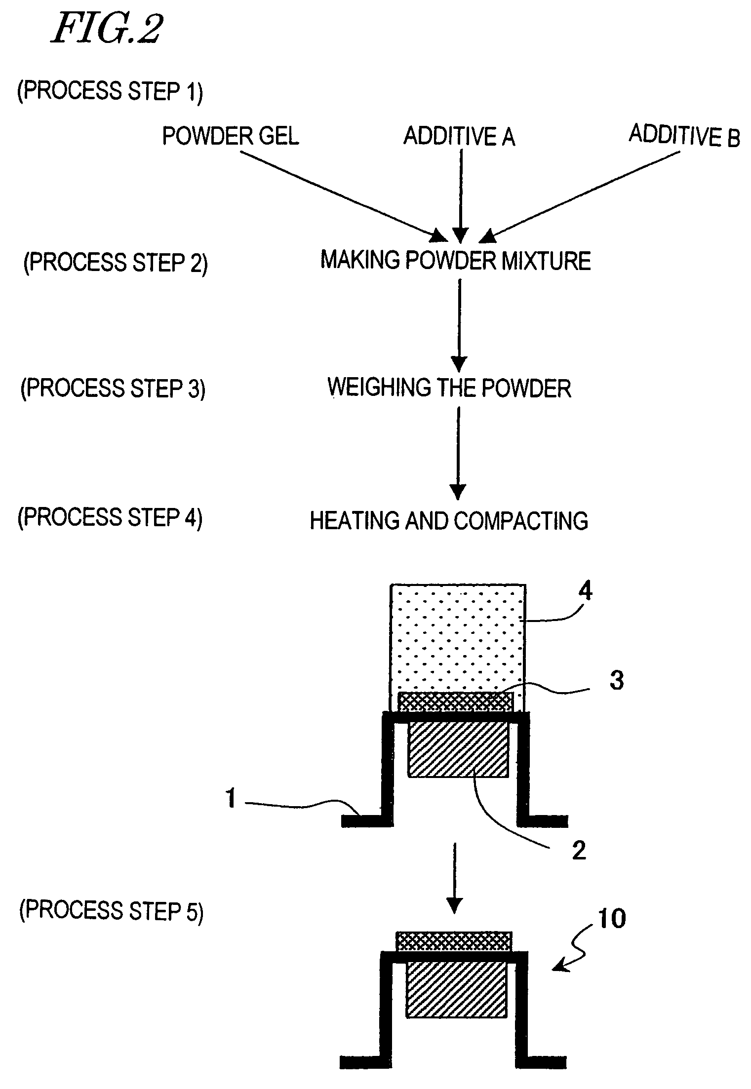
[0100]FIG. 2 is a process diagram showing a manufacturing process of an ultrasonic transducer including an acoustic matching layer according to a first embodiment of the present invention. Hereinafter, this manufacturing process will be described in the order of Process Steps Nos. 1, 2, 3 and 4.[0101]Process Step No. 1: preparing a low-density powder dry gel of a porous body (with a density of about 200 kg / M3 to about 400 kg / m3) and additives A and B, which account for about 10 mass % of the overall mixture. In this process step, the dry gel to be prepared does not have to be a powder but may be blocks. The dry gel may be a silica dry gel with an average pore diameter of 20 nm. The additive A may be a polypropylene powder. And the additive B may be a glass wool with a fiber diameter of about 10 μm;[0102]Process Step No. 2: putting the dry gel and additives A and B into the same container, mixing them together and pulverizing the mixture, thereby obtaining a fine powder. This process...

embodiment 2

[0110]FIG. 3 is a process diagram showing a manufacturing process of an ultrasonic transducer including an acoustic matching layer according to a second embodiment of the present invention. Hereinafter, this manufacturing process will be described in the order of Process Steps Nos. 1, 2, 3, 4 and 5.[0111]Process Step No. 1: preparing a low-density powder dry gel of a porous body and additive A, which accounts for about 10 mass % of the overall mixture. In this process step, the additive A includes an epoxy resin powder as a main agent (which will be referred to herein as “additive A1”) and a polyamide resin powder as a curing agent for the epoxy resin (which will be referred to herein as “additive A2”);[0112]Process Step No. 2: putting the dry gel and additives A1 and A2 into the same container, mixing them together and pulverizing the mixture, thereby obtaining a fine powder;[0113]Process Step No. 3: weighing the powder mixture consisting of the low-density powder dry gel and addit...

embodiment 3

[0120]FIG. 4 is a process diagram showing a manufacturing process of an ultrasonic transducer including an acoustic matching layer according to a third embodiment of the present invention. Hereinafter, this manufacturing process will be described in the order of Process Steps Nos. 1, 2, 3 and 4.[0121]Process Step No. 1: bonding a piezoelectric layer 2 to a case 1 with a known adhesive, for example;[0122]Process Step No. 2: providing an O-ring 31 of an organic film, for example, as a thickness regulating member (control member) on the case 1 so as to control the thickness of the acoustic matching layer at about λ / 4;[0123]Process Step No. 3: dripping, as a sol solution, a silicate aqueous solution with a pH of 9 to 10 onto the case 1 on which the O-ring 31 has been disposed, adjusting the pH of the silicate aqueous solution to 5.5, and then forming a wet gel 33 with the assembly capped with a flat plate 32. In gelling this silicate aqueous solution, an OH group on the surface of the c...


PUM


Abstract

An acoustic matching layer according to the present invention includes a powder of a dry gel. The dry gel preferably has a density of 500 kg / m3 or less and an average pore diameter of 100 nm or less. By using the dry gel powder, a variation in the property of the acoustic matching layer can be reduced.

Description

CROSS-REFERENCE TO RELATED APPLICATION[0001]This application is a Section 371 of International Application No. PCT / JP03 / 00812, filed Jan. 28, 2003 the disclosure of which is incorporated herein by reference.TECHNICAL FIELD[0002]The present invention relates to an acoustic matching layer for use to match acoustic impedance, an ultrasonic transducer to transmit or receive an ultrasonic wave, a method of making the acoustic matching layer, a method for fabricating the ultrasonic transducer, and an ultrasonic flowmeter including the ultrasonic transducer.BACKGROUND ART[0003]FIG. 10 is a cross-sectional view schematically showing a configuration for a conventional ultrasonic generator (which will also be referred to herein as a “piezoelectric vibrator”) 10. The ultrasonic generator 10 includes a case 1, a piezoelectric layer (vibrating means) 2 and an acoustic impedance matching layer (or matching means, which will be referred to herein as an “acoustic matching layer”). The case 1 and th...

Claims


Application Information

Patent Timeline
Patent Type & Authority Patents(United States)
IPC IPC(8): G01F1/66G10K11/02
CPCG01F1/662G10K11/02G01F1/66
Inventor HASHIMOTO, KAZUHIKOHASHIDA, TAKASHISUZUKI, MASAAKIHASHIMOTO, MASAHIKONAGAHARA, HIDETOMOSHIRAISHI, SEIGOTAKAHARA, NORIHISA
Owner PANASONIC CORP
Why Eureka
Try Eureka