Glass material manufacturing method and glass material manufacturing device
a manufacturing method and glass technology, applied in glass making apparatus, glass reforming apparatus, manufacturing tools, etc., can solve the problems of crystallization precipitation, containerless levitation techniques can reduce the progression of crystallization, etc., and achieve excellent homogeneity
- Summary
- Abstract
- Description
- Claims
- Application Information
AI Technical Summary
Benefits of technology
Problems solved by technology
Method used
Image
Examples
fourth embodiment
[0073]FIG. 7 is a schematic cross-sectional view of a glass material manufacturing device according to a fourth embodiment. FIG. 8 is a schematic plan view showing a portion of the glass material manufacturing device according to the fourth embodiment.
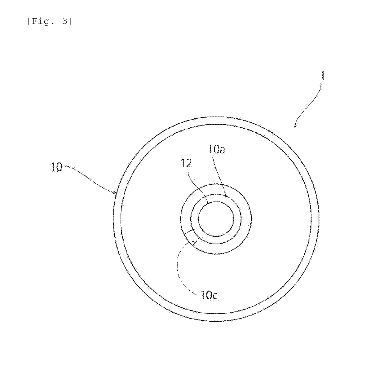
[0074]In the fourth embodiment, a plurality of control gas jet nozzles 10d having their respective control gas jet holes 10c are arranged at approximately regular intervals along the circumferential direction. Each control gas jet nozzle 10d extends along the vertical direction. Therefore, control gas is jetted along an opposite (downward) direction to the (upward) direction of jetting of the levitation gas. Because the plurality of control gas jet nozzles 10d are arranged so that control gas jetted from their respective control gas jet nozzles 10d hits the side surface of the block 12 of glass raw material, the positional change of the molten glass obtained by melting the block 12 of glass raw material can be effectively restricted.
fifth embodiment
[0075]FIG. 9 is a schematic cross-sectional view of a glass material manufacturing device according to a fifth embodiment.
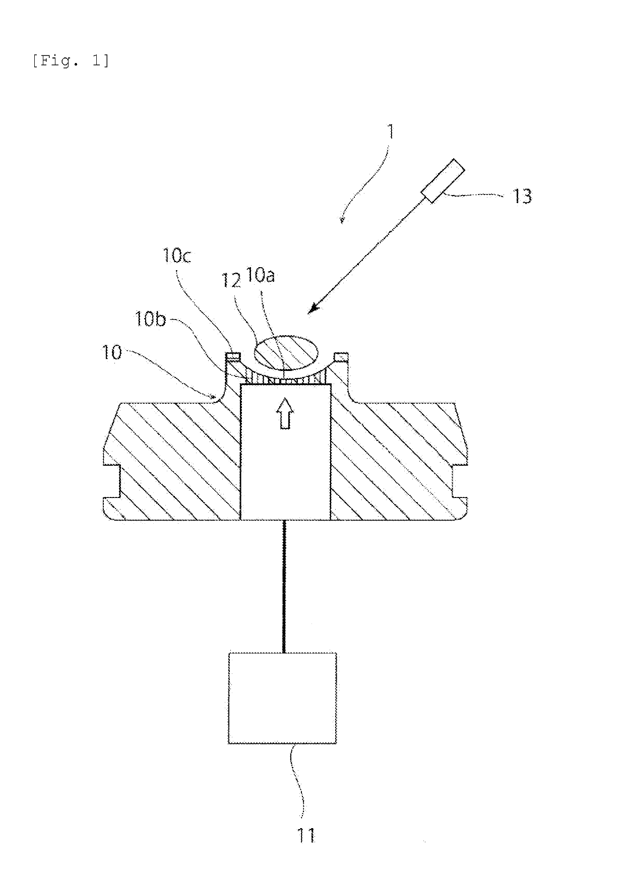
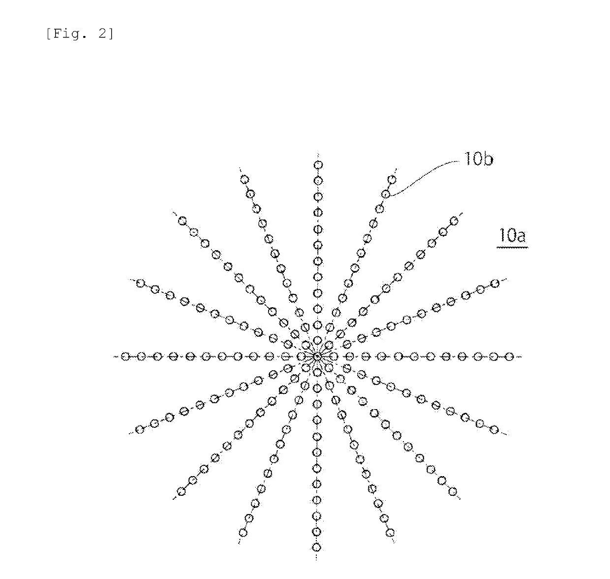
[0076]In the first to fourth embodiments, a description has been given of an example where a plurality of levitation gas jet holes 10b open on the forming surface 10a. However, the present invention is not limited to this configuration. For example, like a glass material manufacturing device shown in FIG. 9, a single gas jet hole 10b opening at the center of the forming surface 10a may be provided. Even with a single levitation gas jet hole 10b, the block 12 of glass raw material or the molten glass can be held above the forming surface 10a of the forming die 10 by levitation gas jetted through the levitation gas jet hole 10b connected to a gas supply mechanism 11.
[0077](2) Second Glass Material Manufacturing Method
First Embodiment
[0078]FIG. 10 is a schematic cross-sectional view of a glass material manufacturing device 1a according to a first embodiment. As show...
first embodiment
[0095]In this embodiment, like the first embodiment of the second glass material manufacturing method, a glass material is manufactured using the manufacturing device 1a shown in FIG. 10.
[0096]As the gas, the same type as that used in the first embodiment of the first glass material manufacturing method can be used.
[0097]Next, a description will be given of a glass material manufacturing method using the manufacturing device 1a. What is performed in this embodiment are: a melting step of placing a block 12 of glass raw material on the forming surface 10a of the forming die 10, melting the block 12 of glass raw material by irradiating the block 12 of glass raw material with laser light from the applicator 13 while jetting gas through the gas jet holes 10a opening on the forming surface 10a, thus obtaining a molten glass, and then homogenizing the molten glass; and a cooling step of cooling the molten glass to obtain a glass material. In the melting step, the irradiation with the lase...
PUM
| Property | Measurement | Unit |
|---|---|---|
| flow rate L3 | aaaaa | aaaaa |
| flow rate L1 | aaaaa | aaaaa |
| flow rate | aaaaa | aaaaa |
Abstract
Description
Claims
Application Information
 - R&D
- Intellectual Property
- Life Sciences
- Materials
- Tech Scout
- Unparalleled Data Quality
- Higher Quality Content
- 60% Fewer Hallucinations
Browse by: Latest US Patents, China's latest patents, Technical Efficacy Thesaurus, Application Domain, Technology Topic, Popular Technical Reports.
© 2025 PatSnap. All rights reserved.Legal|Privacy policy|Modern Slavery Act Transparency Statement|Sitemap|About US| Contact US: help@patsnap.com


