
Tissue engineering scaffolds

a technology of tissue engineering and scaffolds, applied in the field of tissue engineering scaffolds, can solve the problems and achieve the effect of limited ability of cells to interact and organize themselves into functioning tissues

Inactive Publication Date: 2009-08-18
RGT UNIV OF MICHIGAN
View PDF11 Cites 75 Cited by
  • Summary
  • Abstract
  • Description
  • Claims
  • Application Information

AI Technical Summary

Benefits of technology

The present invention relates to methods and compositions for producing scaffolds for tissue engineering. More specifically, the invention relates to controlling the pore structure of porous polymer scaffolds. The invention involves using fusible particles, such as salt crystals, to create a framework for the scaffold, which is then infused with a biodegradable or non-biodegradable polymer to create the scaffold with controlled pore interconnectivity and size. The invention also includes methods for controlling the degree of fusion and the duration of treatment conditions. The resulting scaffolds have improved pore size and ease of production.

Problems solved by technology

When grown on two-dimensional surfaces, the ability of cells to interact and organize themselves into functioning tissues is limited.

Method used


Image

  • Tissue engineering scaffolds
  • Tissue engineering scaffolds
  • Tissue engineering scaffolds

Examples


example 1

[0087]In this example, NaCl frames and biodegradable polymer scaffolds are produced. The salt particles (Mallinkrodt, Paris, Ky.) were sieved to yield a range of sizes. NaCl crystals of a diameter of about 250-425 μm were used.

[0088]Porous scaffolds were prepared either by solvent casting / particulate leaching, or gas foaming / particulate leaching processes using NaCl as the particulate porogen. The solvent cast scaffolds were prepared essentially as described by Mikos, A. G., et al. (“Preparation and characterization of poly(L-lactic acid) foams”Polymer 35:1068, 1994; which is incorporated herein by reference). NaCl molds were made by subjecting NaCl crystals (diameter of about 250-425 μm) to 95% humidity for periods from 0-24 hr to achieve fusion of NaCl crystals prior to solvent casting. A closed, water-jacketed cell culture incubator (Forma Scientific, Inc.) held at 37° C. was used to create a 95% humidity environment for fusion of NaCl crystals.

[0089]Poly(lactide-co-glycolide) (P...

example 2

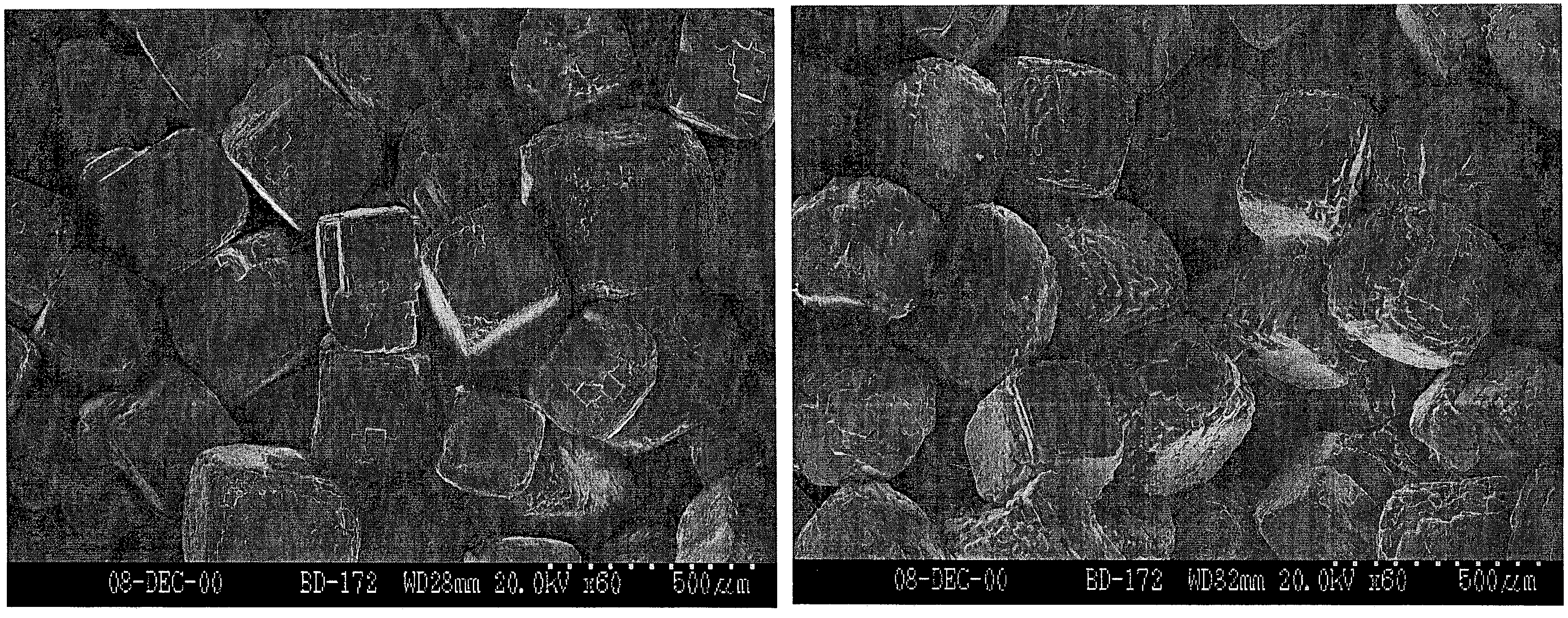
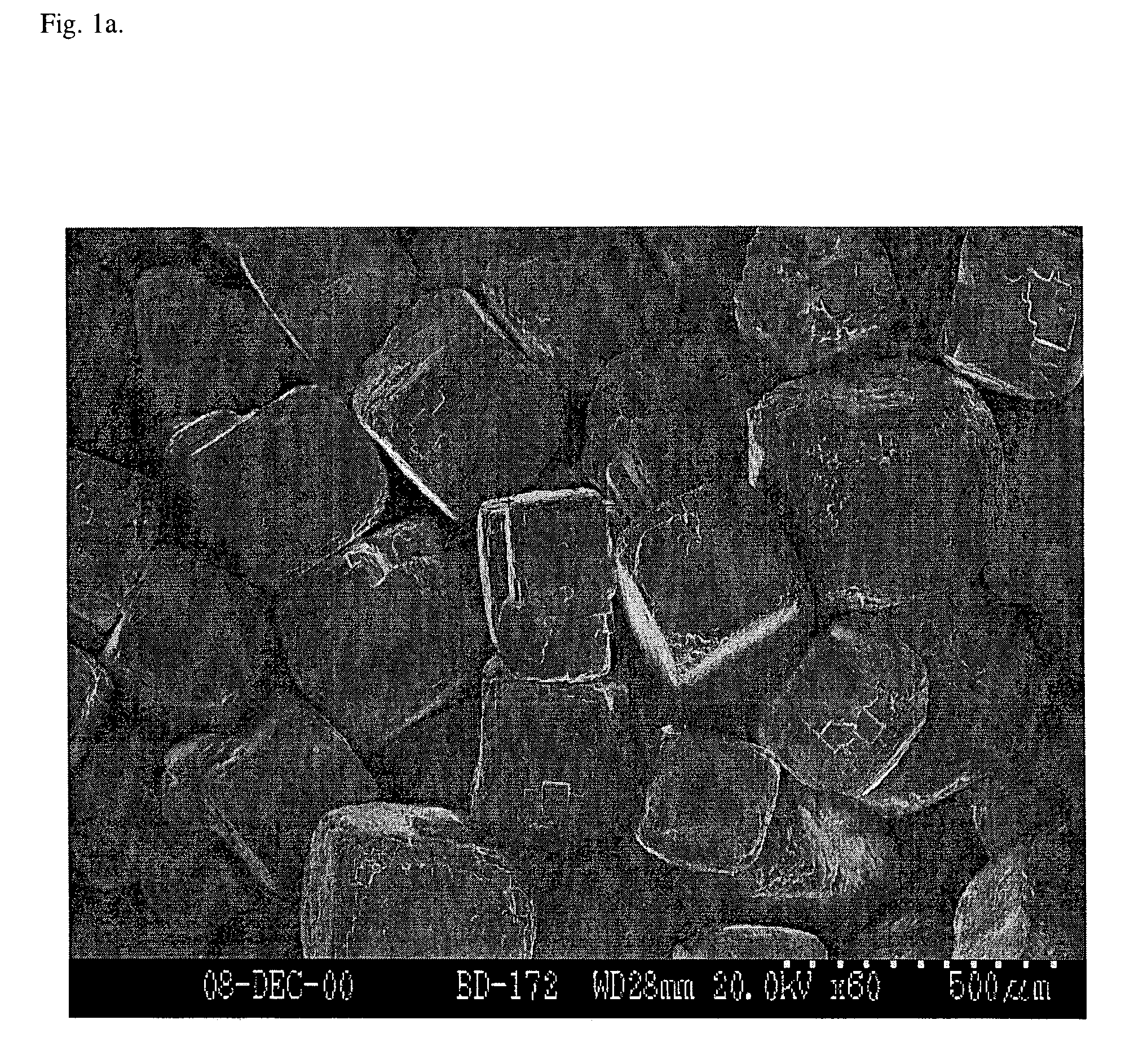
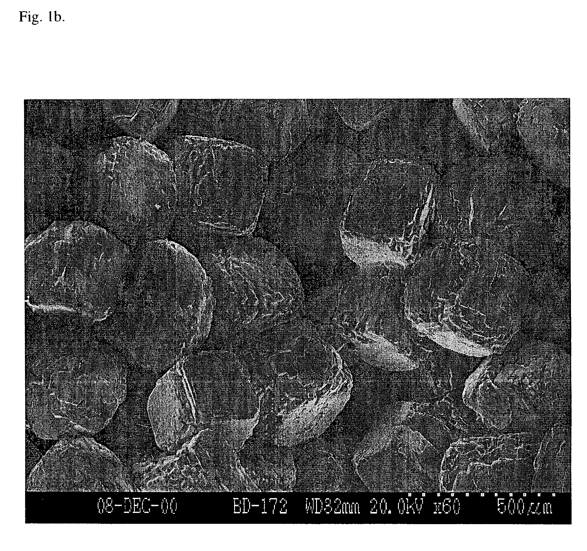
[0092]In this example, the scaffolds are characterized. Incubation of NaCl crystals in 95% humidity resulted in fusion of the crystals, creating a highly interconnected NaCl matrix (FIG. 1a-b). Fused salt molds were bisected and imaged prior to solvent casting to observe the extent of NaCl crystal fusion. In addition, polymer scaffolds were bisected after preparation via freeze fracture. A carbon coating was evaporated onto the surface of each bisected salt mold and polymer scaffold, and samples were imaged under high vacuum using a Hitachi S-3200N SEM operating at 20-30 kV. Fusion of salt crystals prior to addition of PLG in chloroform (solvent casting) resulted in enhanced pore interconnectivity within the scaffold. The pore structure within the scaffolds (FIG. 2) appears similar to the structure of the fused salt matrix (FIG. 1a-b), as expected. Pores within the cross section of 1 hr salt fusion (SF) samples display a defined pore structure with intermittent holes in pore walls, ...

example 3

[0096]In this example, the scaffolds of the present invention are use for the culture of cells. The scaffold is sterilized by gamma radiation, ethylene oxide or cold sterilants. Cells are seeded on to the scaffold in an appropriate culture medium with any necessary growth factors, if needed. Cell culture media may be replaced by batch feeding or by perfusion methods. Sterility is maintained at all times.


PUM

PropertyMeasurementUnit
humidityaaaaaaaaaa
humidityaaaaaaaaaa
humidityaaaaaaaaaa

Abstract

The present invention relates to methods and compositions for the production of scaffolds, such scaffolds to be used for a variety of purposes, including tissue engineering. More specifically, the present invention relates to the use of fused crystals, such as fused salt crystals to form a framework. The methods for producing the scaffolds of this invention improve the porosity, interconnectivity and ease of manufacture as compared to prior art methods.

Description

[0001]This application for patent under 35 USC § 111(a) claims priority to Provisional Application Ser. No. 60 / 345,775 filed on Jan. 2, 2002 under USC § 111(b).[0002]This invention was made in part with government support under grant R01-DE-13349 and training grant T32 GM 08353, both from the National Institute of Health. The government has certain rights in the invention.FIELD OF THE INVENTION[0003]The present invention relates to methods and compositions for the production of scaffolds to be used for tissue engineering. More specifically, the present invention relates to the control of pore structure of porous polymer scaffolds.BACKGROUND[0004]Tissue engineering involves the use of living cells to develop biological substitutes for tissue replacement. However, in order for tissue engineering to be practical, scaffolds must be developed that allow for tissue growth that approximates natural tissue growth.[0005]Several techniques have been employed to develop tissue engineering scaf...

Claims


Application Information

Patent Timeline
Patent Type & Authority Patents(United States)
IPC IPC(8): A61F2/00A61L27/18A61L27/00A61L27/38A61L27/56A61L31/06A61L31/14
CPCA61L27/18A61L27/38A61L27/56A61L31/06A61L31/146C08L67/04
Inventor MURPHY, WILLIAM L.DENNIS, ROBERT G.MOONEY, DAVID J.
Owner RGT UNIV OF MICHIGAN
Learn More