Contact spring

a contact spring and spring technology, applied in the direction of contact surface shape/structure, snap-action arrangement, agriculture tools and machines, etc., can solve the problems of frequent maintenance of the contact spring, prone to wear, variation etc., to achieve stable switching operation and reduce variations in the stroke and load characteristics.

Active Publication Date: 2005-03-10
FUJI ELECTRONICS IND
View PDF11 Cites 0 Cited by
  • Summary
  • Abstract
  • Description
  • Claims
  • Application Information

AI Technical Summary

Benefits of technology

[0006] Accordingly, it is an object of the invention to provide a contact spring in a small-sized push-button switch which is devised in a contact shape so as to lessen contact obstacle between contacts caused by fine dust, to reduce the variation in load characteristics even if the switch is repetitively operated, and to reduce switch properties even if heat is applied upon completion of a reflow soldering step.
[0010] The following effects can be obtained by the invention. Since plural movable contacts are formed by half-cut working, working strain after working is reduced, different from normal bending working or squeeze working, and click action is not influenced by working strain and hence the movable contact is stabilized, and variation in properties of the movable contact caused by heat after working is reduced. Further, since the mass-production of the dome-shaped contact spring is not made by convex working (press bending working) but by half-cut working (semi-shearing working), a mold is less worn out and the frequent maintenance of the mold is not necessary.
[0012] If the contact springs are formed about a central portion of the movable contact spring in the number of four in total at the central angle of 90 °, even if eccentric load acts on the dome-shaped movable contact spring, the movable contact close to a point on which the eccentric load acts is brought into contact with the fixed contact, a stable switching operation can be secured for a long period of time even if the eccentric load acts on the movable contact spring in all the directions. Further, since the surface of the movable contact facing the fixed contact is formed as a flat surface or a concave surface close to the flat surface, even if the movable contact is repetitively operated, it falls in a copper foil pattern as the fixed contact to some extent but it does not fall in the copper foil to the level deeper than some extent, variations in stroke and in load characteristics can be reduced.

Problems solved by technology

Although the conduction obstacle can be overcome by such a configuration, parts for working a convex of a mold serving as a production facility (press bending working) are prone to wear our, frequent maintenance thereof has been needed.
Further, when the contact spring is allowed to contact or breaks off the fixed contact of the FPC copper foil pattern, the semi-spherical protrusion of the movable contact falls in the copper foil pattern during the repetitive operations of the contact spring, resulting in the occurrence of variations in stroke and load characteristics.
Further, there occurred the problem that working strain remains in a product (dome-shaped contact spring) in the convex working (press bending working) of the dome-shaped protrusion, and this strain is removed when heat is applied after reflow soldering working to largely vary the load characteristics.

Method used


Image

  • Contact spring
  • Contact spring
  • Contact spring

Examples


Embodiment Construction

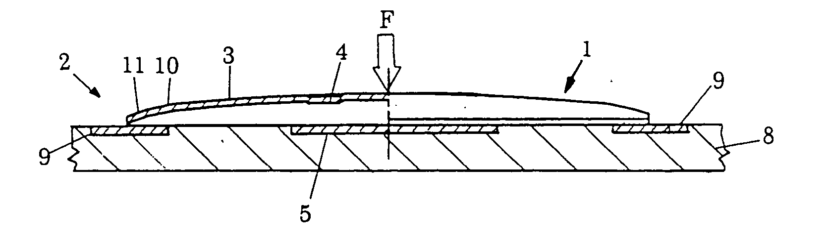
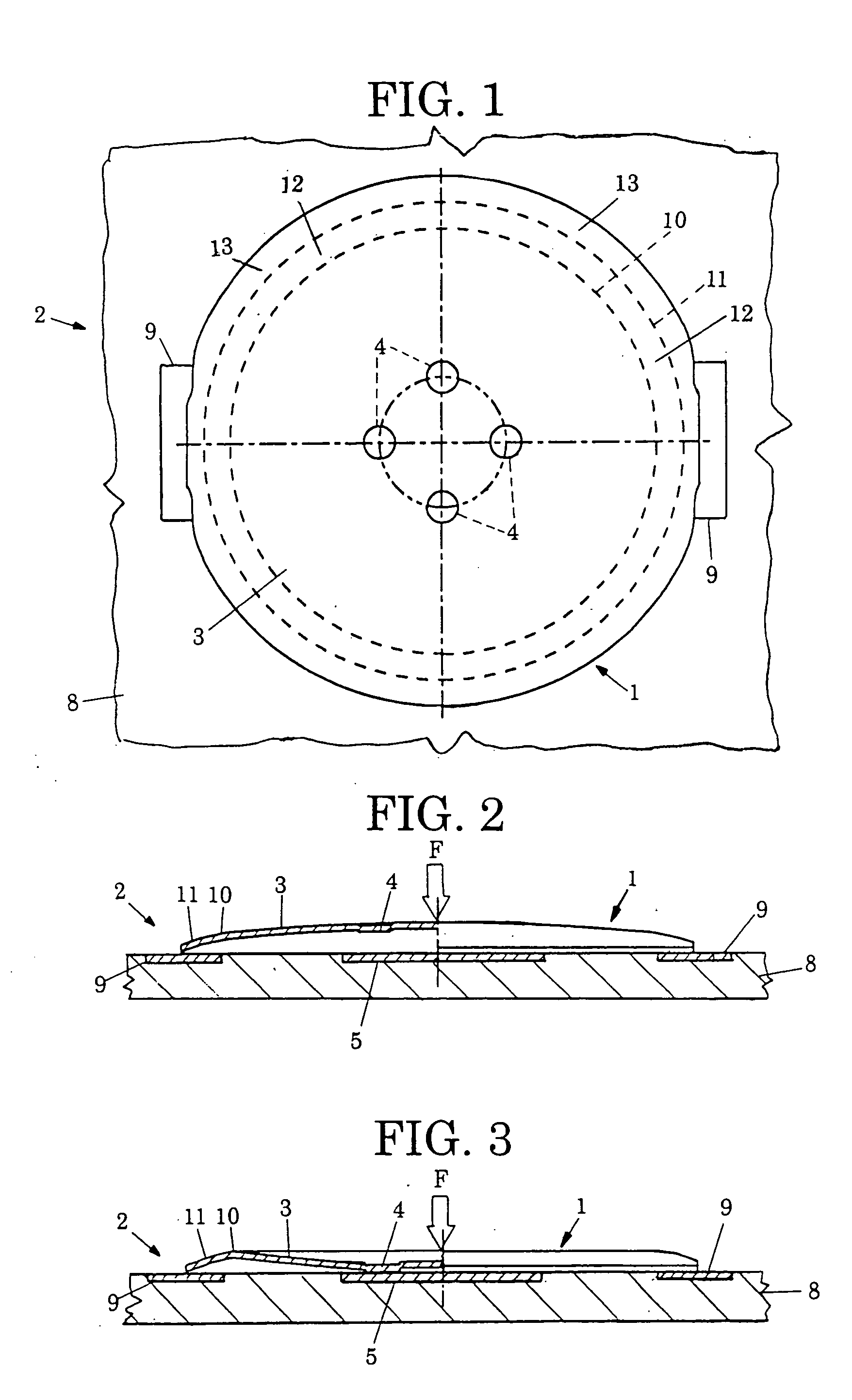
[0020] FIGS. 1 to 5 show a state where a contact spring 1 of the invention is built in a small-sized push-button switch 2. The switch allows the movable contact 4 to contact or break off the contact with an opposed fixed contact 5 to render the movable contact 4 and the fixed contact 5 to be in one of an electrically on or off state. The movable contact spring 3 contacts a conductive pattern 9 of a substrate 8 at a peripheral end along the diametrical line thereof. The fixed contact 5 is formed on the upper surface of the substrate 8, for example, by a part of the conductive pattern 9 and faces the movable contact 4 of the movable contact spring 3 at the inner side thereof. The conductive pattern 9 is formed of a copper foil on the upper surface of the substrate 8, normally by print wiring technique.

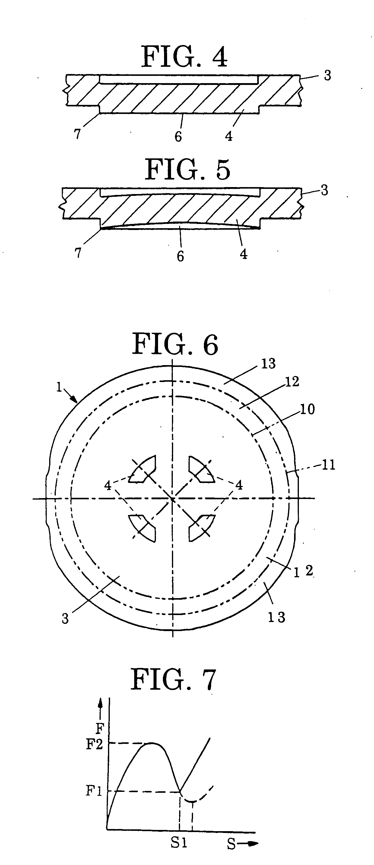
[0021] The contact spring 1 of the invention is configured by the movable contact spring 3 set forth above. The movable contact spring 3 is formed in a spherical dome-shape by a spring ...


PUM


Abstract

There is provided a contact spring in a small-sized push-button switch capable of lessening contact obstacle between contacts caused by fine dust, and reducing variation in load characteristics even if heat is applied thereto or the switch is repetitively operated. The contact spring in the switch for allowing a movable contact provided at an inner side of a movable contact spring to contact or break off the contact with an opposed fixed contact so as to render the movable contact and the fixed contact to be in one of an electrically on or off state, wherein multiple movable contacts are formed by protruding a material of the movable contact spring by a thickness of not more than two thirds of a thickness of the movable contact spring on a circumference about a central portion of the movable contact spring and positioned at an equal central angle relative to the center of the movable contact spring in a direction from an outside to an inner side of the movable contact spring by means of half-cut working while forming a peripheral edge of a protruded contact surface in a sharp blade-shape.

Description

FIELD OF THE INVENTION [0001] The invention relates to an improvement of a contact spring, which is operable by click action (hereinafter simply referred to as contact spring), for use in a small-sized push-button switch. [0002] The contact spring of this type is built in a small-sized push-button switch of electric equipment or electronic equipment such as audio equipment, video equipment, communication equipment such as a portable telephone, measuring equipment and the like. The small-sized push-button switch is configured in accordance with the use thereof as a box type wherein a single or plural contact springs are built in a box or a sheet type wherein many contact springs such as push-button switches of a portable telephone are built in a sheet (FPC pattern sheet). [0003] The movable contact spring is dome-shaped and configured such that a movable contact provided at an inner part thereof is allowed to contact a fixed contact facing the movable contact or to break off the cont...

Claims


Application Information

Patent Timeline
Patent Type & Authority Applications(United States)
IPC IPC(8): H01H1/06H01H5/30H01H13/48
CPCH01H1/06H01H2227/026H01H13/48A01D34/54A01D34/47A01D34/62
Inventor URUSHIBATA, AKIMITSU
Owner FUJI ELECTRONICS IND
Why Eureka
Try Eureka