
Filter, color wheel using the filter, and manufacturing method for the same

Active Publication Date: 2005-11-29
DELTA ELECTRONICS INC
View PDF6 Cites 11 Cited by
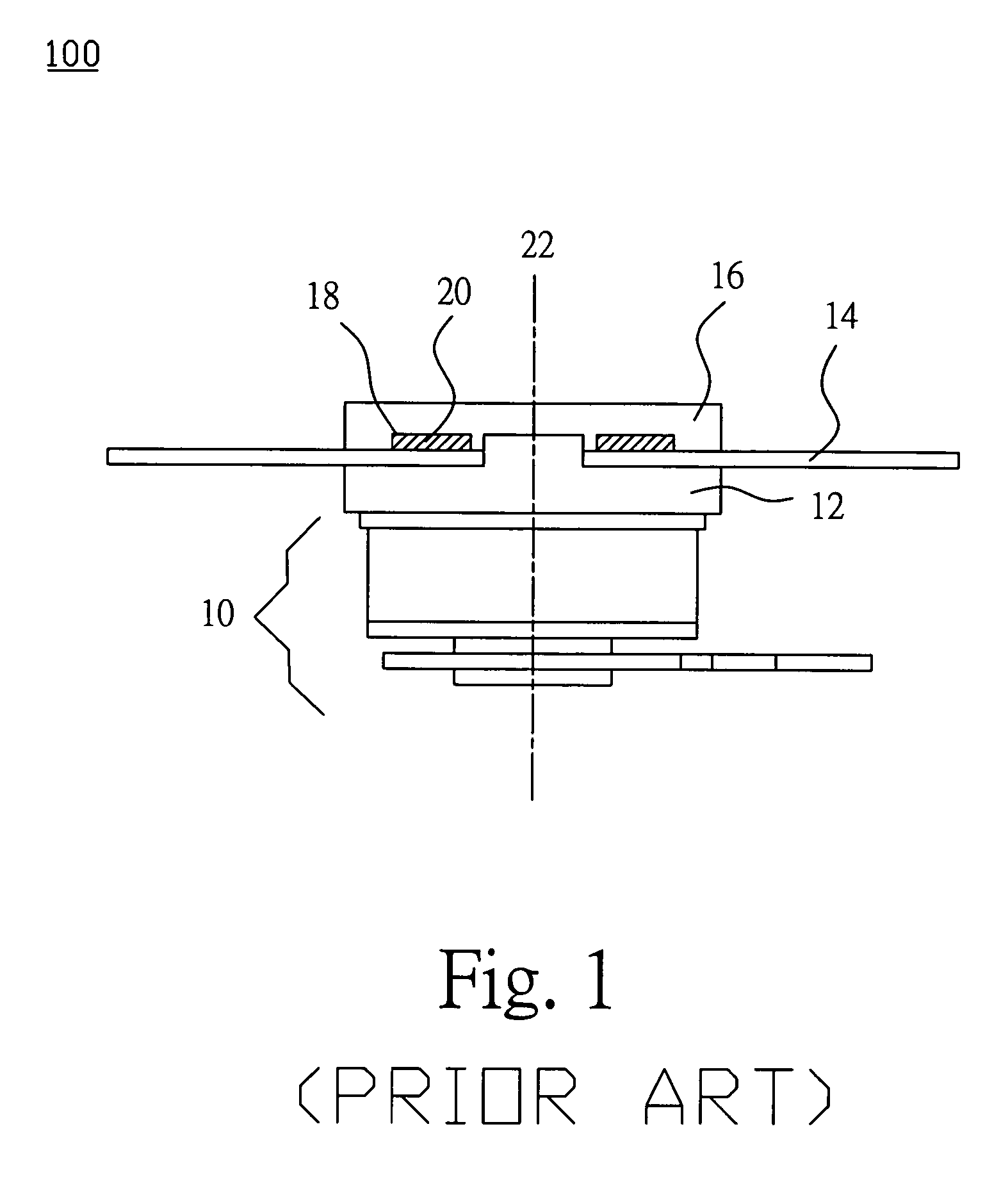
  • Summary
  • Abstract
  • Description
  • Claims
  • Application Information

AI Technical Summary

Benefits of technology

[0010]In view of the foregoing, the invention provides a color wheel to effectively prevent vibrations occurring during high-speed rotations.
[0011]Moreover, the invention provides a method for making the color wheel to prevent simultaneously vibrations and deviations from happening to the filter rotating at high speeds.
[0019]In the above color wheel structure, the filter group and the carriers have corresponding apertures to accommodate the connection component. Therefore, the connection component in. the invention has enough resistance to the sheer force even if it is made of a soft or elastic adhesive agent. The filter group can be avoided from deviation.
[0020]Since the connection component is made of a soft or elastic adhesive, it can effectively absorb vibrations generated during high-speed rotations of the color wheel. The invention is thus able to prevent vibrations and deviations of the filter group in from high-speed rotations and the noises thereof.
[0021]In the disclosed manufacturing method, the filter group and the carriers are connected using the soft or elastic connection components. Thus, the precision can be appropriately relaxed to reduce the costs.

Problems solved by technology

When the color wheel rotates, the color filter is likely to wiggle and deviate due to the centrifugal force.
In particular, when the error between the filter and the carrier is too large, it may result in damages to the filter.
Nonetheless, if the adhesive is hard it is very difficult for the adhesive to absorb vibrations generated when the color filter is rotating at high speeds.
Therefore, there might be noises due to large vibrations at high speeds.
Once the vibration reaches a certain extent, the color filter will break and damage.
The adhesive agent between the carrier element and the filter is likely to overflow to the transparent zone of the filter, resulting in filter pollution.
The polluted part will have a worse optical quality.

Method used


Image

  • Filter, color wheel using the filter, and manufacturing method for the same
  • Filter, color wheel using the filter, and manufacturing method for the same
  • Filter, color wheel using the filter, and manufacturing method for the same

Examples


Embodiment Construction

[0028]The present invention will be apparent from the following detailed description, which proceeds with reference to the accompanying drawings, wherein the same references relate to the same elements.

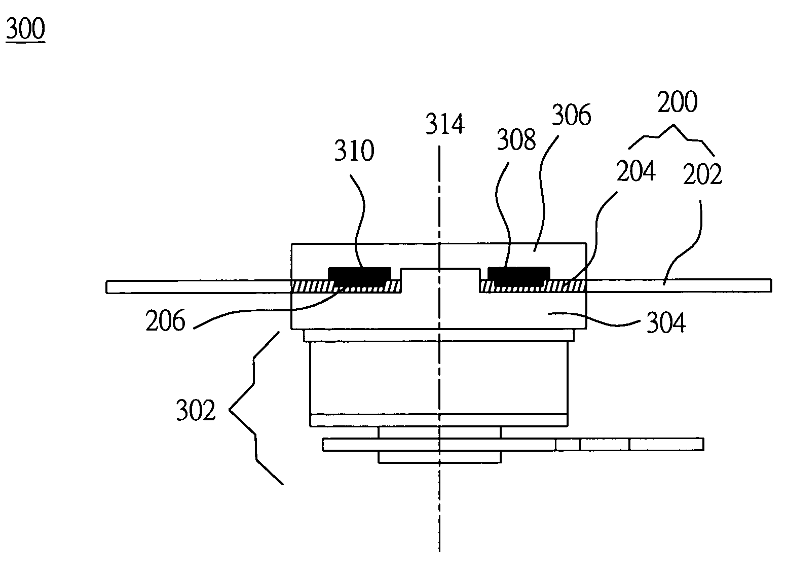
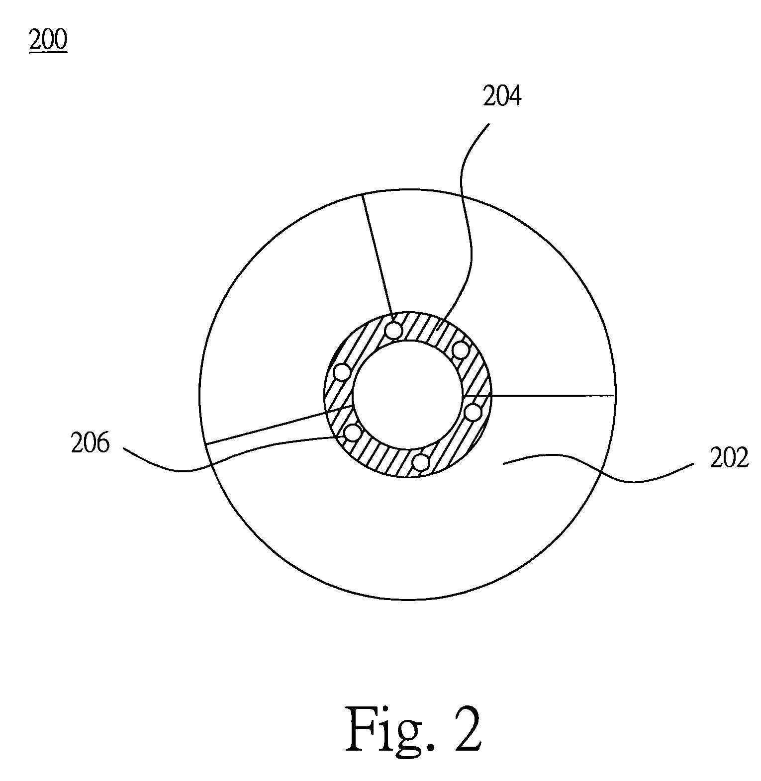
[0029]With reference to FIG. 2, the filter group 200 of the invention is made of one or more filters. For instance, the filter group 200 has a planar annular thin sheet structure. It can be divided into a transparent zone 202 and a filter bonding zone 204. The filter bonding zone 204 has at least one aperture 206 not positioned on a central axial line.

[0030]The transparent zone 202 is used to provide a high penetration rate to change the color of light after the beam of light passes through it. An example of the transparent zone 202 is a zone coated with an optical interferometer film.

[0031]The filer bonding zone 204 is a zone for the filter group 200 to combine with the color wheel or carrier to be described later. The apertures 206 of the filter bonding zone 204 are used for the con...


PUM


Abstract

A color wheel includes a carrier element, a filter group, and a connection component. The carrier element includes a first carrier, and a second carrier. The carrier element rotates around the central axial line. The first carrier has at least one aperture. The filter group has a transparent zone and a filter bonding zone. The filter group and the carrier element share the central axial line. The filter bonding zone has at least one concave zone. The combining component is simultaneously in the apertures of the first carrier and the filter bonding zone to fix the filter bonding zone of the filter group between the first carrier and the second carrier.

Description

BACKGROUND OF THE INVENTION[0001]This Nonprovisional application claims priority under 35 U.S.C. § 119(a) on Patent Application No(s). 092112776 filed in TAIWAN on May 12, 2003, the entire contents of which are hereby incorporated by reference.[0002]1. Field of Invention[0003]The invention relates to a color filter, a color wheel using the color filter, and the method for making the same. In particular, the invention relates to a color wheel with a filter that does not be escaped from a carrier element of the color wheel, and the method for making the color wheel.[0004]2. Related Art[0005]The conventional color wheel structure is composed of a carrier and a planar color filter. When the color wheel rotates, the color filter is likely to wiggle and deviate due to the centrifugal force. In particular, when the error between the filter and the carrier is too large, it may result in damages to the filter.[0006]To solve the above problem, an adhesive means has been proposed to combine th...

Claims


Application Information

Patent Timeline
IPC IPC(8): G02B7/00H04N9/31
CPCH04N9/3197H04N9/3114G02B26/008G02B7/006
Inventor CHANG, SEANCHEN, KENNY
Owner DELTA ELECTRONICS INC
Learn More